ECD SYSTEM Injector Circuit
| DTC Code | DTC Name |
|---|---|
| Injector Circuit |
DESCRIPTION
The injector driver drives the injectors at high speeds with a high-voltage DC/DC converter. The ECM constantly monitors the injector driver and stops the engine if an abnormal condition is detected.
WIRING DIAGRAM
Refer to DTC P0201 (Click here).
CAUTION / NOTICE / HINT
After replacing the ECM, the new ECM needs registration (Click here) and initialization (Click here).
Inspect the fuses of circuits related to this system before performing the following inspection procedure.
PROCEDURE
CHECK TERMINAL VOLTAGE (POWER SOURCE OF INJECTOR DRIVER (EDU))
-
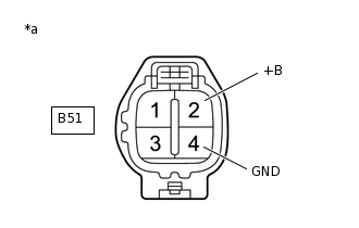
*a
Front view of wire harness connector
(to Injector Driver (EDU))
Disconnect the injector driver (EDU) connector.
Turn the ignition switch to ON.
Measure the voltage according to the value(s) in the table below.
Standard Voltage
Tester Connection
Condition
Specified Condition
B51-2 (+B) - B51-4 (GND)
Ignition switch ON
11 to 14 V
Result
Proceed to
OK
NG
-
CHECK HARNESS AND CONNECTOR (INJECTOR DRIVER (EDU) - BODY GROUND)
Disconnect the injector driver (EDU) connector.
Measure the resistance according to the value(s) in the table below.
Standard Resistance
Tester Connection
Condition
Specified Condition
B51-4 (GND) - Body ground
Always
Below 1 Ω
Result
Proceed to
OK
NG
NG REPAIR OR REPLACE HARNESS OR CONNECTOR
INSPECT EDU RELAY
Inspect the EDU relay.
Result
Proceed to
OK
NG
NG REPLACE EDU RELAY
CHECK TERMINAL VOLTAGE (POWER SOURCE OF EDU RELAY)
-
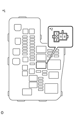
*1
Engine Room Relay Block and Junction Block Assembly
*2
EDU Relay
Remove the EDU relay from the engine room relay block and junction block assembly.
Measure the voltage according to the value(s) in the table below.
Standard Voltage
Tester Connection
Condition
Specified Condition
5 (EDU relay) - Body ground
Always
11 to 14 V
Result
Proceed to
OK
NG
NG REPAIR OR REPLACE HARNESS OR CONNECTOR (BATTERY - EDU RELAY)
-
CHECK HARNESS AND CONNECTOR (INJECTOR DRIVER (EDU) - EDU RELAY)
Disconnect the injector driver (EDU) connector.
Remove the EDU relay from the engine room relay block and junction block assembly.
Measure the resistance according to the value(s) in the table below.
Standard Resistance
Tester Connection
Condition
Specified Condition
B51-2 (+B) - 3 (EDU relay)
Always
Below 1 Ω
B51-2 (+B) or 3 (EDU relay) - Body ground
Always
10 kΩ or higher
Result
Proceed to
OK
NG
NG REPAIR OR REPLACE HARNESS OR CONNECTOR
CHECK HARNESS AND CONNECTOR (ECM - EDU RELAY)
Disconnect the ECM connector.
Remove the EDU relay from the engine room relay block and junction block assembly.
Measure the resistance according to the value(s) in the table below.
Standard Resistance
Tester Connection
Condition
Specified Condition
A61-44 (IREL) - 1 (EDU relay)
Always
Below 1 Ω
A61-44 (IREL) or 1 (EDU relay) - Body ground
Always
10 kΩ or higher
Result
Proceed to
OK
NG
NG REPAIR OR REPLACE HARNESS OR CONNECTOR
CHECK HARNESS AND CONNECTOR (EDU RELAY - EFI-MAIN NO. 2 RELAY)
Remove the EDU relay and EFI-MAIN NO. 2 relay from the engine room relay block and junction block assembly.
Measure the resistance according to the value(s) in the table below.
Standard Resistance
Tester Connection
Condition
Specified Condition
2 (EDU relay) - 3 (EFI-MAIN NO. 2 relay)
Always
Below 1 Ω
2 (EDU relay) or 3 (EFI-MAIN NO. 2 relay) - Body ground
Always
10 kΩ or higher
Result
Proceed to
OK
NG
NG REPAIR OR REPLACE HARNESS OR CONNECTOR
INSPECT EFI-MAIN NO. 2 RELAY
Inspect the EFI-MAIN NO. 2 relay.
Result
Proceed to
OK
NG
NG REPLACE EFI-MAIN NO. 2 RELAY
CHECK TERMINAL VOLTAGE (POWER SOURCE OF EFI-MAIN NO. 2 RELAY)
-
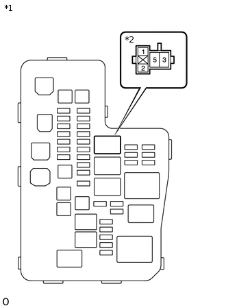
*1
Engine Room Relay Block and Junction Block Assembly
*2
EFI-MAIN NO. 2 relay
Remove the EFI-MAIN NO. 2 relay from the engine room relay block and junction block assembly.
Measure the voltage according to the value(s) in the table below.
Standard Voltage
Tester Connection
Condition
Specified Condition
5 (EFI-MAIN NO. 2 relay) - Body ground
Always
11 to 14 V
Result
Proceed to
OK
NG
NG REPAIR OR REPLACE HARNESS OR CONNECTOR (BATTERY - EFI-MAIN NO. 2 RELAY)
-
CHECK HARNESS AND CONNECTOR (EFI-MAIN NO. 2 - BODY GROUND)
Remove the EFI-MAIN NO. 2 relay from the engine room relay block and junction block assembly.
Measure the resistance according to the value(s) in the table below.
Standard Resistance
Tester Connection
Condition
Specified Condition
2 (EFI-MAIN NO. 2 relay) - Body ground
Always
Below 1 Ω
Result
Proceed to
OK
NG
NG REPAIR OR REPLACE HARNESS OR CONNECTOR
CHECK HARNESS AND CONNECTOR (ECM - EFI-MAIN NO. 2 RELAY)
Disconnect the ECM connector.
Remove the EFI-MAIN NO. 2 relay from the engine room relay block and junction block assembly.
Measure the resistance according to the value(s) in the table below.
Standard Resistance
Tester Connection
Condition
Specified Condition
A61-45 (MREL) - 1 (EFI-MAIN NO. 2 relay)
Always
Below 1 Ω
A61-45 (MREL) or 1 (EFI-MAIN NO. 2 relay) - Body ground
Always
10 kΩ or higher
Result
Proceed to
OK
NG
NG REPAIR OR REPLACE HARNESS OR CONNECTOR