LIGHTING SYSTEM Headlight Leveling ECU Power Source Circuit
| DTC Code | DTC Name |
|---|---|
| Headlight Leveling ECU Power Source Circuit |
DESCRIPTION
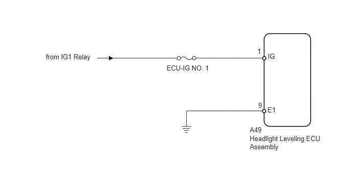
This circuit detects the state of the ignition switch, and sends it to the headlight leveling ECU.
WIRING DIAGRAM
CAUTION / NOTICE / HINT
Inspect the fuses for circuits related to this system before performing the following inspection procedure.
PROCEDURE
READ VALUE USING INTELLIGENT TESTER
Using the intelligent tester, read the Data List (Click here).
Table 1. HL Auto Leveling (Headlight Leveling ECU) Tester Display
Measurement Item/Range
Normal Condition
Diagnostic Note
+B
Ignition power supply voltage value / 0 to 19.75 V
11 to 14 V
-
OK
The display is as specified in the normal condition column.
CHECK HARNESS AND CONNECTOR (BATTERY - HEADLIGHT LEVELING ECU ASSEMBLY)
Disconnect the A49 headlight leveling ECU connector.
Measure the voltage according to the value(s) in the table below.
Standard Voltage
Tester Connection
Switch Condition
Specified Condition
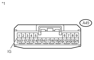
A49-1 (IG) - Body ground
Ignition switch ON
11 to 14 V
A49-1 (IG) - Body ground
Ignition switch off
Below 1 V
Table 2. Text in Illustration *1
Front view of wire harness connector
(to Headlight Leveling ECU Assembly)
REPAIR OR REPLACE HARNESS OR CONNECTOR
CHECK HARNESS AND CONNECTOR (HEADLIGHT LEVELING ECU ASSEMBLY - BODY GROUND)
Measure the resistance according to the value(s) in the table below.
Standard Resistance
Tester Connection
Condition
Specified Condition
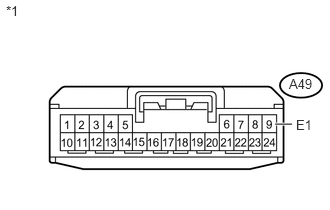
A49-9 (E1) - Body ground
Always
Below 1 Ω
Table 3. Text in Illustration *1
Front view of wire harness connector
(to Headlight Leveling ECU Assembly)
Table 4. Result Result
Proceed to
NG
A
OK (for LHD)
B
OK (for RHD)
C
REPAIR OR REPLACE HARNESS OR CONNECTOR