INTAKE SYSTEM DETAILS
-
CONSTRUCTION
-
Diesel Throttle Body Assembly
-
A diesel throttle valve equipped with a rotary solenoid type throttle control motor is used to improve EGR performance and to reduce the vibration and noise when stopping the engine. The rotary solenoid type throttle control motor makes the diesel throttle valve respond quickly.
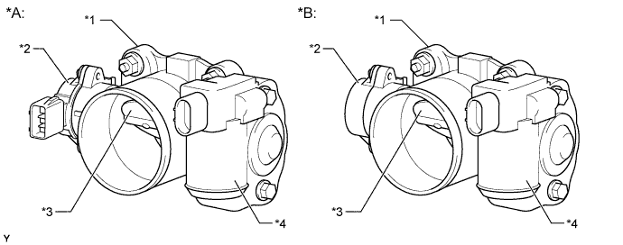
Text in Illustration *A Models Compliant with EURO 5 Emission Regulations *B Except Models Compliant with EURO 5 Emission Regulations *1 Diesel Throttle Body Assembly *2 Throttle Position Sensor *3 Diesel Throttle Valve *4 Throttle Control Motor
-
-
Intake Manifold
-
An intake manifold provided with an air intake chamber is used in order to reduce the swirl variances between the cylinders.
-
On the models compliant with EURO 4 emission regulations and models compliant with EURO 2 emission regulations with variable nozzle vane type turbocharger, a vacuum-actuated swirl control valve is provided in one of the 2 intake ports provided for each cylinder. The swirl control valve consists of a stainless steel shaft and an actuator, which are integrated in the valve. The swirl control valve with 2-stage control is used.
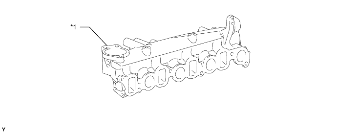
Text in Illustration (Models Compliant with EURO 5 Emission Regulations:) *1 Intake Manifold - - 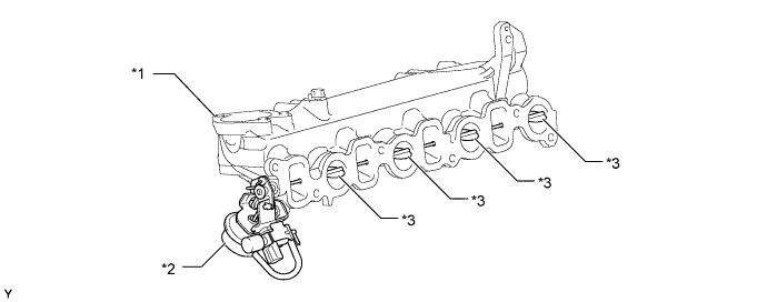
Text in Illustration (Models Compliant with EURO 4 Emission Regulations and Models Compliant with EURO 2 Emission Regulations with Variable Nozzle Vane Type Turbocharger:) *1 Intake Manifold *2 Actuator *3 Swirl Control Valve - - 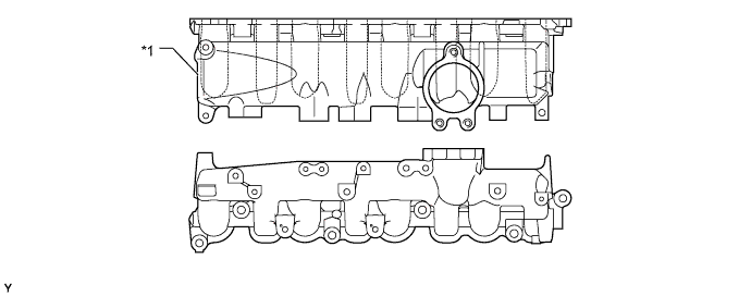
Text in Illustration (Models Compliant with EURO 2 Emission Regulations with Wastegate Valve Type Turbocharger and Models Non-compliant with Emission Regulations:) *1 Intake Manifold - -
-
-
Intercooler Assembly (Models with Intercooler)
-
An air-cooled intercooler is used in order to lower the intake air temperature, improve engine performance, and achieve cleaner exhaust gas emissions. It is located directly on top of the engine.
-
The intercooler and the inlet tank are made of aluminum and the outlet tank is made of plastic for weight reduction.
-
A dual construction, high-frequency cavity resonator is used for the pipe between the turbocharger and the intercooler.
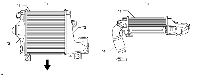
Text in Illustration (Models Compliant with EURO 5 Emission Regulations:) *1 Intercooler Assembly *2 Inlet Tank *3 Outlet Tank *4 High-frequency Cavity Resonator *a View from Top Side *b View from Front Side 
Front - - 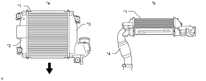
Text in Illustration (Models Compliant with EURO 4 Emission Regulations and Models Compliant with EURO 2 Emission Regulations with Variable Nozzle Vane Type Turbocharger:) *1 Intercooler Assembly *2 Inlet Tank *3 Outlet Tank *4 High-frequency Cavity Resonator *a View from Top Side *b View from Front Side Front - -
-
-
Turbocharger Sub-assembly (Models with Variable Nozzle Vane Type Turbocharger)
-
A variable nozzle vane type turbocharger is used. A water jacket is provided in the bearing housing to improve the cooling performance of the turbocharger.
-
This turbocharger has achieved great improvements in low-speed torque, maximum output, fuel consumption, and emission reduction. These improvements have been accomplished through variable control of the nozzle vane position, and an optimal velocity of the exhaust gas inflow to the turbine at all times in response to the engine condition.
-
The ECM outputs a signal to the turbocharger sub-assembly (via the turbo motor driver*), which actuates the DC motor, to control the nozzle vane position.
-
*: Except models compliant with EURO 5 emission regulations
-
-
The variable nozzle vane type turbocharger consists primarily of a compressor wheel, turbine wheel, nozzle vane, unison ring, drive arm, driven arm, DC motor, linkage and nozzle vane position sensor.
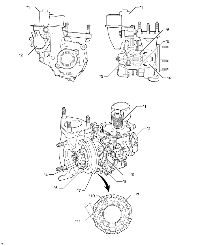
Text in Illustration *1 DC Motor *2 Nozzle Vane Position Sensor *3 Compressor Wheel *4 Turbine Wheel *5 Water Jacket *6 Nozzle Vane *7 Unison Ring *8 Full-close Stopper *9 Linkage *10 Driven Arm *11 Drive Arm - - Tech Tips
-
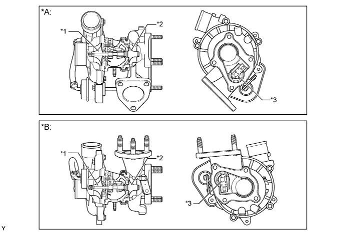
To control the nozzle vane position, the ECM*1 or turbo motor driver*2 renders the contact position of the linkage with the full-close stopper (thus fully closing the nozzle vane) as the zero point for the nozzle vane position sensor.
-
*1: Models compliant with EURO 5 emission regulations
-
*2: Except models compliant with EURO 5 emission regulations
-
If the turbocharger has been reinstalled or replaced, turn the ignition switch from ON to off once, and make sure that the linkage comes in contact with the full-close stopper.
-
The full-close stopper position, which is adjusted at the factory at the time of shipment, is not serviceable in the field. For this reason, if the linkage does not come in contact with the full-close stopper during an inspection, the turbocharger assembly must be replaced. Never attempt to loosen or tighten the lock nut of the full-close stopper because it will adversely affect the performance of the engine.
-
For details, refer to the corresponding Repair Manual for this model.

Text in Illustration *1 Linkage *2 Full-close Stopper *3 Lock Nut - - *a Open *b Closed
-
-
-
Turbocharger Sub-assembly (Models with Wastegate Valve Type Turbocharger)
-
A lightweight and compact air-cooled type turbocharger is used. To control the turbo pressure, this turbocharger is provided with a wastegate valve and an actuator that operates mechanically in accordance with the turbo pressure.
Text in Illustration *A Models without Intercooler *B Models with Intercooler *1 Compressor Wheel *2 Turbine Wheel *3 Wastegate Valve - -
-
-
-
OPERATION
-
Turbocharger Sub-assembly (Models with Variable Nozzle Vane Type Turbocharger)
-
The exhaust gas from the exhaust manifold goes through the nozzle vane inside the turbo charger housing, and flows to the exhaust pipe through the turbine. The speed of the turbine (supercharging pressure) differs depending on the flow velocity of the exhaust gas going through the turbine and the flow velocity of the exhaust gas is controlled by the opening. In such a time of idling, when the exhaust gas is less, the nozzle vane is almost fully closed, but as there is a slight clearance between the vanes, the exhaust gas flows through this clearance to the exhaust pipe. Therefore, there is no bypass.

Text in Illustration *1 Nozzle Vane - - 
Intake Air Exhaust Gas -
When the engine is running in a low speed range, the DC motor presses down the linkage by a signal from the ECM (via the turbo motor driver*). The tip of the linkage rotates the unison ring counterclockwise through a drive arm. The unison ring contains a driven arm, which is placed through the cutout portion of the unison ring. This driven arm also moves in the direction of the rotation of the unison ring. The fulcrum of the driven arm is an axis that is integrated with the nozzle vane behind the plate. When the driven arm moves counterclockwise, the nozzle vane moves toward the closing direction. This results in increasing the velocity of the exhaust gas flowing to the turbine, as well as the speed of the turbine. As a result, torque is improved when the engine is running at low speeds.
-
*: Except models compliant with EURO 5 emission regulations
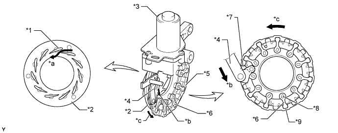
Text in Illustration *1 Nozzle Vane *2 Plate *3 DC Motor *4 Linkage *5 Unison Ring *6 Driven Arm *7 Drive Arm *8 Fulcrum *9 Cutout Portion of Unison Ring - - *a Gas Flow *b Movement of Linkage *c Rotation Direction of Unison Ring - - -
-
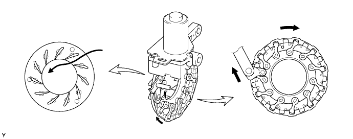
When the engine is running in a medium-to-high speed range, the DC motor pulls up the linkage by a signal from the ECM (via the turbo motor driver*). With this, the driven arm moves clockwise and this opens the nozzle vane and holds the specified supercharging pressure, thus lowering the back pressure and improving the output and fuel consumption.
-
*: Except models compliant with EURO 5 emission regulations
-
-
-