ROOF SUNSHADE SYSTEM TERMINALS OF ECU
-
CHECK SLIDING ROOF DRIVE GEAR SUB-ASSEMBLY (SLIDING ROOF ECU)
-
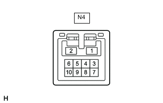
Disconnect the N4 sliding roof drive gear sub-assembly (sliding roof ECU) connector.
-
Measure the resistance and voltage according to the value(s) in the table below.
Tester Connection Wiring Color Terminal Description Condition Specified Condition N4-1 (B) - Body ground G - Body ground Battery power supply Always 11 to 14 V N4-2 (E) - Body ground W-B - Body ground Ground Always Below 1 Ω -
Reconnect the N4 sliding roof drive gear sub-assembly (sliding roof ECU) connector.
-
Measure the voltage according to the value(s) in the table below.
Tester Connection Wiring Color Terminal Description Condition Specified Condition N4-5 (UP) - Body ground G - Body ground Sliding roof switch (OPEN) signal Engine switch on (IG), fronr roof sunshade switch (OPEN) off → on 11 to 14 V → Below 1 V N4-9 (DWN) - Body ground L - Body ground Sliding roof switch (CLOSE) signal Engine switch on (IG), fronr roof sunshade switch (CLOSE) off → on 11 to 14 V → Below 1 V -
Measure the pulse according to the value(s) in the table below.
Tester Connection Wiring Color Terminal Description Condition Specified Condition N4-3 (MPX2) - Body ground B - Body ground LIN communication line Engine switch on (IG) Pulse generation N4-7 (MPX1) - Body ground V - Body ground LIN communication line Engine switch on (IG) Pulse generation
-
-
CHECK SLIDING ROOF DRIVE GEAR ASSEMBLY (FRONT ROOF SUNSHADE ECU)
-
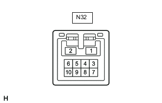
Disconnect the N32 sliding roof drive gear assembly (front roof sunshade ECU) connector.
-
Measure the resistance and voltage according to the value(s) in the table below.
Tester Connection Wiring Color Terminal Description Condition Specified Condition N32-1 (B) - Body ground W - Body ground Battery power supply Always 11 to 14 V N32-2 (E) - Body ground LA - Body ground Ground Always Below 1 Ω -
Reconnect the N32 sliding roof drive gear assembly (front roof sunshade ECU) connector.
-
Measure the pulse according to the value(s) in the table below.
Tester Connection Wiring Color Terminal Description Condition Specified Condition N32-3 (MPX2) - Body ground B - Body ground LIN communication line Engine switch on (IG) Pulse generation
-
-
CHECK SLIDING ROOF DRIVE GEAR ASSEMBLY (REAR ROOF SUNSHADE ECU)
-
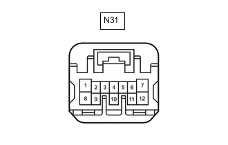
Disconnect the N31 sliding roof drive gear assembly (rear roof sunshade ECU) connector.
-
Measure the resistance and voltage according to the value(s) in the table below.
Tester Connection Wiring Color Terminal Description Condition Specified Condition N31-7 (B) - Body ground R - Body ground Battery power supply Always 11 to 14 V N31-1 (E) - Body ground W-B - Body ground Ground Always Below 1 Ω -
Reconnect the N31 sliding roof drive gear assembly (rear roof sunshade ECU) connector.
-
Measure the voltage according to the value(s) in the table below.
Tester Connection Wiring Color Terminal Description Condition Specified Condition N31-4 (SW) - Body ground B - Body ground Rear roof sunshade switch (OPEN) signal Engine switch on (IG), rear roof sunshade switch off → on 11 to 14 V → Below 1 V -
Measure the pulse according to the value(s) in the table below.
Tester Connection Wiring Color Terminal Description Condition Specified Condition N31-3 (MPX1) - Body ground V - Body ground LIN communication line Engine switch on (IG) Pulse generation
-