METER / GAUGE SYSTEM, Diagnostic DTC:B1507 and B1508
| DTC Code | DTC Name |
|---|---|
| B1507 | Open in Turn Signal Circuit |
| B1508 | Short in Turn Signal / Hazard Flasher Circuit |
DESCRIPTION
These DTCs are stored when the combination meter assembly detects an open in a turn signal light circuit, a short in a turn signal light circuit, or a short in the hazard warning light circuit.
DTC No. |
Detection Item |
DTC Detection Condition |
Trouble Area |
|---|---|---|---|
B1507 |
Open in Turn Signal Circuit |
Both conditions are met:
|
|
B1508 |
Short in Turn Signal / Hazard Flasher Circuit |
Both conditions are met:
|
|
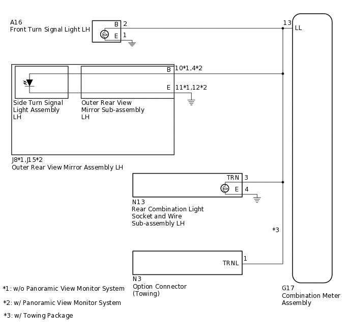
WIRING DIAGRAM
for LH Side
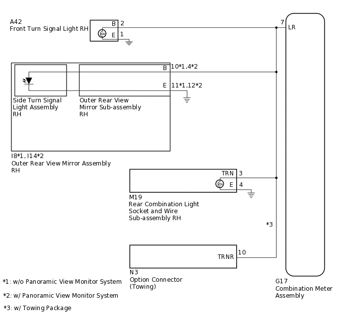
for RH Side
CAUTION / NOTICE / HINT
Inspect the bulbs for this system before performing the following procedure.
When replacing the combination meter assembly, make sure to replace it with a new one.
PROCEDURE
CHECK FOR DTC
Clear the DTCs.
Body Electrical > Combination Meter > Clear DTCs
Check for DTCs.
Body Electrical > Combination Meter > Trouble Codes
Result
Proceed to
DTC B1507 or B1508 output does not occur
DTC B1507 or B1508 is output
DTC B1507 or B1508 output does not occur USE SIMULATION METHOD TO CHECK
CONFIRM MALFUNCTIONING LIGHT
Check the malfunctioning turn signal light.
Result
Result
Proceed to
LH side turn signal light does not illuminate.
A
RH side turn signal light does not illuminate.
B
B CHECK HARNESS AND CONNECTOR (TURN SIGNAL CIRCUIT RH)Click here
CHECK HARNESS AND CONNECTOR (TURN SIGNAL CIRCUIT LH)
*1: w/o Panoramic View Monitor System
*2: w/o Panoramic View Monitor System
*3: w/ Towing Package
Disconnect the G17 combination meter assembly connector.
Disconnect the A16 front turn signal light LH connector.
Disconnect the J8*1 or J15*2 rear combination light socket wire sub-assembly LH connector.
Disconnect the N13 outer rear view mirror sub-assembly LH connector.
w/ Towing Package:
Disconnect the N3 option connector (Towing).
Measure the resistance according to the value(s) in the table below.
Standard Resistance
Tester Connection
Condition
Specified Condition
G17-13 (LL) - A16-2 (B)
Always
Below 1 Ω
G17-13 (LL) - J8-10 (B)
Always
Below 1 Ω
G17-13 (LL) - J15-4 (B)
Always
Below 1 Ω
G17-13 (LL) - N13-3 (TRN)
Always
Below 1 Ω
G17-13 (LL) - N3-1 (TRNL)
Always
Below 1 Ω
A16-1 (E) - Body Ground
Always
Below 1 Ω
J8-11 (E) - Body Ground
Always
Below 1 Ω
J15-12 (E) - Body Ground
Always
Below 1 Ω
N13-4 (E) - Body Ground
Always
Below 1 Ω
G17-13 (LL) or A16-2 (B) - Body ground
Always
10 kΩ or higher
G17-13 (LL) or J8-10 (B) - Body ground
Always
10 kΩ or higher
G17-13 (LL) or J15-4 (B) - Body ground
Always
10 kΩ or higher
G17-13 (LL) or N13-3 (TRN) - Body ground
Always
10 kΩ or higher
G17-13 (LL) or N3-1 (TRNL) - Body ground
Always
10 kΩ or higher
Result
Proceed to
OK
NG
NG REPAIR OR REPLACE HARNESS OR CONNECTOR
INSPECT OUTER REAR VIEW MIRROR ASSEMBLY LH
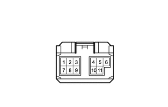
Remove the outer rear view mirror assembly LH.
Connect the positive (+) lead from the battery to terminal 10 and the negative (-) lead to terminal 11, and check that the light comes on.
Result
Proceed to
Light comes on
Light not comes on
INSPECT SIDE TURN SIGNAL LIGHT ASSEMBLY LH
Remove the side turn signal light assembly LH.
Inspect the side turn signal light assembly LH.
Result
Proceed to
OK
NG
CHECK HARNESS AND CONNECTOR (TURN SIGNAL CIRCUIT RH)
*1: w/o Panoramic View Monitor System
*2: w/o Panoramic View Monitor System
*3: w/ Towing Package
Disconnect the G17 combination meter assembly connector.
Disconnect the A42 front turn signal light RH connector.
Disconnect the I8*1 or I14*2 rear combination light socket wire sub-assembly RH connector.
Disconnect the M19 outer rear view mirror sub-assembly RH connector.
w/ Towing Package:
Disconnect the N3 option connector (Towing).
Measure the resistance according to the value(s) in the table below.
Standard Resistance
Tester Connection
Condition
Specified Condition
G17-7 (LR) - A42-2 (B)
Always
Below 1 Ω
G17-7 (LR) - I8-10 (B)
Always
Below 1 Ω
G17-7 (LR) - I14-4 (B)
Always
Below 1 Ω
G17-7 (LR) - M19-3 (TRN)
Always
Below 1 Ω
G17-7 (LR) - N3-10 (TRNR)
Always
Below 1 Ω
A42-1 (E) - Body Ground
Always
Below 1 Ω
I8-11 (E) - Body Ground
Always
Below 1 Ω
I14-12 (E) - Body Ground
Always
Below 1 Ω
M19-4 (E) - Body Ground
Always
Below 1 Ω
G17-7 (LR) or A42-2 (B) - Body ground
Always
10 kΩ or higher
G17-7 (LR) or I8-10 (B) - Body ground
Always
10 kΩ or higher
G17-7 (LR) or I14-4 (B) - Body ground
Always
10 kΩ or higher
G17-7 (LR) or M19-3 (TRN) - Body ground
Always
10 kΩ or higher
G17-7 (LR) or N3-10 (TRNR) - Body ground
Always
10 kΩ or higher
Result
Proceed to
OK
NG
NG REPAIR OR REPLACE HARNESS OR CONNECTOR
INSPECT OUTER REAR VIEW MIRROR ASSEMBLY RH
Remove the outer rear view mirror assembly RH.
Connect the positive (+) lead from the battery to terminal 10 and the negative (-) lead to terminal 11, and check that the light comes on.
Result
Proceed to
Light comes on
Light not comes on
INSPECT SIDE TURN SIGNAL LIGHT ASSEMBLY RH
Remove the side turn signal light assembly LH.
Inspect the side turn signal light assembly LH.
Result
Proceed to
OK
NG