CAN COMMUNICATION SYSTEM(w/o Central Gateway ECU) DIAGNOSIS SYSTEM
ECUS OR SENSORS WHICH COMMUNICATE THROUGH CAN COMMUNICATION SYSTEM
V Bus
Combination meter assembly
Certification ECU (smart key ECU assembly)*1
Steering sensor (spiral cable with sensor sub-assembly)*2
Radio and display receiver assembly*3
Airbag sensor assembly
Power steering ECU assembly
Air conditioning amplifier assembly*4
Clearance warning ECU assembly*5
Engine stop and start ECU*6
Brake actuator assembly
Main body ECU (multiplex network body ECU)
Headlight leveling ECU assembly*7
Headlight swivel ECU assembly*8
ECM
Pre-crash safety city sensor*9
Telematics transceiver*10
CHECK FOR INSTALLED SYSTEMS (ECUS AND SENSORS) THAT USE CAN COMMUNICATION
The systems (ECUs and sensors) that use CAN communication vary depending on the vehicle and optional equipment. Check which systems (ECUs and sensors) are installed to the vehicle.
ECU / Sensor Name
GTS Display
Applicability
ECM
ECM (Engine)
TCM*1
Vehicles for 1ND-TV
ECM
ECM (Engine)
Vehicles for 1NR-FE, 1ZR-FE, 1WW, 2ZR-FE or 8NR-FTS
ECM
ECM (Engine)
VALVEMATIC Driver*2
Power Management*3
Vehicles for 1ZR-FAE
Main body ECU (multiplex network body ECU)
Main Body
Installed on all vehicles
Brake actuator assembly
Skid Control (ABS/VSC/TRAC)
Installed on all vehicles
Power steering ECU assembly
Power Steering (EPS)
Installed on all vehicles
Air conditioning amplifier assembly
Air Conditioning Amplifier
Vehicles with Air Conditioning System
Airbag sensor assembly
Airbag
Installed on all vehicles
Certification ECU (smart key ECU assembly)
Certification (Smart)
Vehicles with Entry and Start System
Steering sensor (spiral cable with sensor sub-assembly)
Spiral cable (Steering Angle Sensor)
Vehicles with VSC
Combination meter assembly
Combination Meter
Installed on all vehicles
Radio and display receiver assembly
Display and Navigation (AVN1)
Vehicles for Radio and Display Type
Clearance warning ECU assembly
Clearance Warning (Clearance Sonar2)
Vehicles with Simple Intelligent Parking Assist System
Engine stop and start ECU
Stop & Go
Vehicles with Stop and Start System
Headlight leveling ECU assembly
Headlight swivel (AFS)
Vehicles with Automatic Headlight Beam Level Control System for Sedan
Headlight swivel ECU assembly
Headlight swivel (AFS)
Vehicles with Automatic Headlight Beam Level Control System except Sedan
Pre-crash safety city sensor
Front Camera Module
Vehicles with Toyota Safety Sense
Telematics transceiver
DCM
Vehicles with Manual (SOS) Switch
Tip:The names of ECUs and sensors shown on the GTS display may differ from those shown in the DTC Table by ECU section.
*1: w/ Multi-mode Manual Transaxle System
*2: If "ECM (Engine)" is displayed but "VALVEMATIC Driver" is not displayed, a local CAN communication error between the ECM and continuously variable valve lift controller assembly is suspected. (Output DTC: U011B)
*3: If "ECM (Engine)" is displayed but "Power Management" is not displayed, a local CAN communication error between the ECM and generator control ECU assembly is suspected.
The generator control ECU assembly is displayed as "Power Management" when a CAN bus check is performed.
CAN BUS CHECK
Tip:The ECUs and sensors that are properly connected to the CAN communication system can be displayed using the GTS.
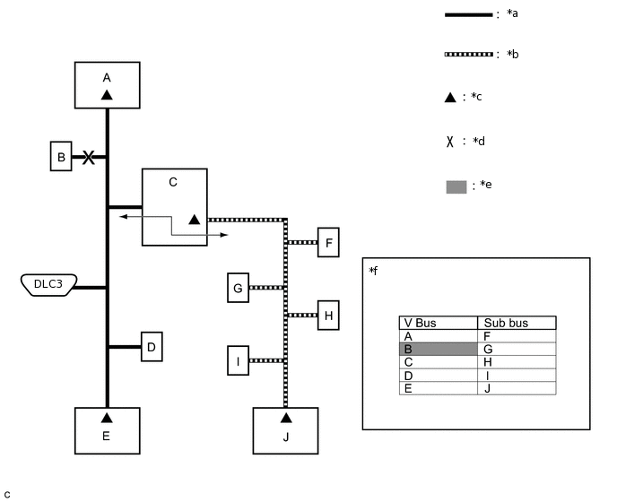
Using the GTS, select the CAN Bus Check screen.
CAN Bus Check
Note:It may be possible to select buses that do not have ECUs or sensors from the bus selection pull-down menu. This is not a malfunction. (This occurs when optional devices are not on a sub bus that is monitored by a gateway function equipped ECU.)
In the bus selection pull down menu, all buses applicable to the model are displayed (e.g. LIN communication buses are also displayed). Therefore, refer to the wiring diagrams to check the names of sub buses for CAN communication.
Tip:Different connection statuses are indicated by the background color of ECUs and sensors that are displayed.
Table 1. Explanation of CAN Bus Check Screen Bus Type
Background Color
Connection Status
V Bus
White
Communication has been normal since the start of the CAN bus check.
Yellow
Communication stop occurred at least once since the start of the CAN bus check, but communication is currently occurring (unstable communication).
Red
Communication was established at least once since the start of the CAN bus check, but communication is currently not occurring (unstable communication).
Not displayed
Communication stop has continued since the start of the CAN bus check.*1
Sub Bus
(gateway function equipped ECU that does not have history of connected ECUs)*2
White
Communication has been normal since the start of the CAN bus check.
Yellow
Communication stop occurred at least once since the start of the CAN bus check, but communication is currently occurring (unstable communication).
Red
Communication was established at least once since the start of the CAN bus check, but communication is currently not occurring (unstable communication).
Not displayed
Communication stop has continued since the start of the CAN bus check.*1
Sub Bus
(gateway function equipped ECU that has history of connected ECUs)*3
White
Communication has been normal since the start of the CAN bus check.
Yellow
Communication stop occurred at least once since the start of the CAN bus check, but communication is currently occurring (unstable communication).
Red
Currently not communicating (either of the following):
Communication stop has continued since the start of the CAN bus check.
Communication was established at least once since the start of the CAN bus check, but communication is currently not occurring.
Not displayed
Either of the following:
If a gateway function equipped ECU cannot communicate, the sub bus and ECUs connected to the sub bus will not be displayed.
If no ECUs are connected to the sub bus, ''There is no system found on the Communication Bus'' will be displayed.
Tip:Gateway function equipped ECUs relay signals between the ECUs connected to the different buses.
*1: ECUs that are present in the vehicle but are not displayed on the CAN Bus Check screen.
*2: Gateway function equipped ECU that does not memorize the sub bus ECUs that are connected to it.
*3: Gateway function equipped ECU that memorizes the sub bus ECUs that are connected to it.
If none of the connected ECUs are displayed, or there is no response from the vehicle to the GTS, check the DLC3 branch and the V bus main bus lines for a malfunction.
Observe the connection response screen for approximately 2 minutes to check for a change in connection status of the connected ECUs and sensors.
Tip:If an open occurs in one of the lines of a CAN branch (except DLC3), output from the other branch line (the line that is not open) will be unstable and it may interfere with the response (display) of other ECUs and sensors.
If the connection status changes during the inspection, repair the open in the branch line of the ECU or sensor that does not respond (is not detected) and then perform the CAN bus check again.
HOW TO INTERPRET CAN BUS CHECK SCREEN
When a communication stop is currently occurring, the probable malfunctioning part can be determined from the CAN bus check and by using the following methods.
Note:The following CAN bus wiring diagram is provided only as an example. This wiring diagram is different from the actual wiring diagram for this vehicle.
Tip:When a communication stop is currently occurring, it is easier to determine the probable malfunctioning part from the CAN bus check rather than from communication DTCs.
Wait for approximately 2 minutes after turning the ignition switch to ON (or simulate the driving conditions that enable the malfunction to be reproduced) and select CAN bus check. Then observe the communication status of each ECU on the screen.
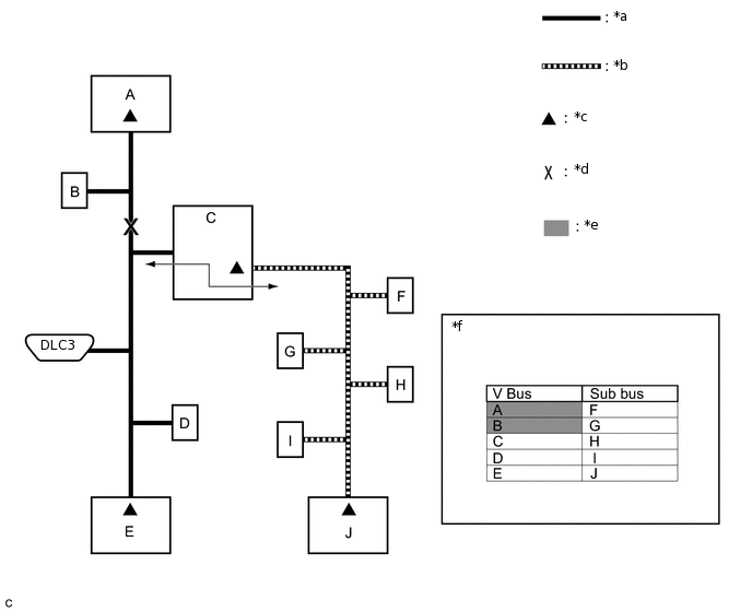
If a communication error of only 1 ECU or sensor is indicated on the CAN Bus Check screen, a communication stop of the ECU or sensor is suspected.
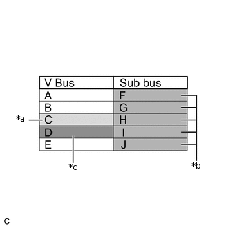
Example: Open in both CAN branch lines of ECU B on the V bus
*a
V Bus
*b
Sub Bus
*c
Terminating Resistor
*d
Location of Malfunction
*e
Not displayed or background color changes to red or yellow
*f
CAN Bus Check Screen
Tip:When there are communication stops, ECUs are present in the vehicle even though they are not displayed on the CAN Bus Check screen.
-
*a
Background color periodically changes to yellow or red
*b
Not displayed or background color is yellow or red
*c
Not displayed
If communication errors for multiple ECUs or sensors are indicated on the CAN Bus Check screen, then a communication stop of the ECU or sensor that shows a more serious communication stop (an ECU or sensor which is not displayed) is suspected.
Example: Open in a CAN branch line for ECU D on the V bus
Table 2. Explanation of CAN Bus Check Screen Bus Type
Background Color
Connection Status
V Bus
White
Communication has been normal since the start of the CAN bus check.
Yellow
Communication stop occurred at least once since the start of the CAN bus check, but communication is currently occurring (unstable communication).
Red
Communication was established at least once since the start of the CAN bus check, but communication is currently not occurring (unstable communication).
Not displayed
Communication stop has continued since the start of the CAN bus check.*1
Sub Bus
(gateway function equipped ECU that does not have history of connected ECUs)*2
White
Communication has been normal since the start of the CAN bus check.
Yellow
Communication stop occurred at least once since the start of the CAN bus check, but communication is currently occurring (unstable communication).
Red
Communication was established at least once since the start of the CAN bus check, but communication is currently not occurring (unstable communication).
Not displayed
Communication stop has continued since the start of the CAN bus check.*1
Sub Bus
(gateway function equipped ECU that has history of connected ECUs)*3
White
Communication has been normal since the start of the CAN bus check.
Yellow
Communication stop occurred at least once since the start of the CAN bus check, but communication is currently occurring (unstable communication).
Red
Currently not communicating (either of the following):
Communication stop has continued since the start of the CAN bus check.
Communication was established at least once since the start of the CAN bus check, but communication is currently not occurring.
Not displayed
Either of the following:
If a gateway function equipped ECU cannot communicate, the sub bus and ECUs connected to the sub bus will not be displayed.
If no ECUs are connected to the sub bus, ''There is no system found on the Communication Bus'' will be displayed.
Tip:Gateway function equipped ECUs relay signals between the ECUs connected to the different buses.
*1: ECUs that are present in the vehicle but are not displayed on the CAN Bus Check screen.
*2: Gateway function equipped ECU that does not memorize the sub bus ECUs that are connected to it.
*3: Gateway function equipped ECU that memorizes the sub bus ECUs that are connected to it.
The example of the CAN Bus Check screen in the illustration shows the result of electrical noise on the CAN bus which is caused by an open in a CAN branch line of ECU D (output from the other branch line is unstable) and the communication of ECU C is also unstable. In addition, in this example, ECU C is equipped with a gateway function. Therefore, communication is also unstable between the sub bus ECUs of ECU C and the V bus.
The example in the illustration shows that ECU D is not displayed on the CAN Bus Check screen. This indicates a more significant communication stop. In this case, a communication stop of ECU D is suspected.
-
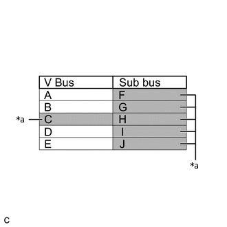
*a
Not displayed or background color changes to red
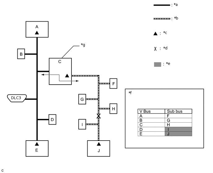
If a communication error is indicated on both the V bus and sub bus on the CAN Bus Check screen, suspect any communication stop displayed for the V bus first.
Example: Open in both CAN branch lines of ECU C on the V bus
Tip:In the CAN bus check, it is possible to confirm the communication status of ECUs connected to the V bus after connecting the GTS to the DLC3. As for sub buses, it is possible to confirm which sub bus connected ECUs can communicate with a gateway function equipped ECU on the V bus.
If a gateway function equipped ECU has a communication error, ECUs connected to the gateway function equipped ECU are also affected, and communication stops will be indicated.
The CAN Bus Check screen in the illustration shows that ECU C has a gateway function and a communication stop in ECU C is suspected.
-
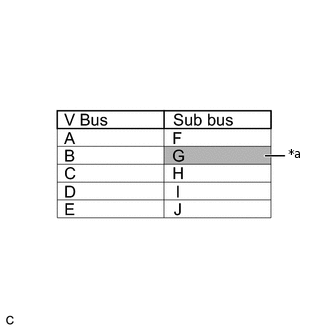
*a
Background color changes to red
If the CAN Bus Check screen indicates a communication stop only in the sub bus, a communication stop in the sub bus is suspected.
Example: Open in both CAN branch lines of ECU G on the sub bus
Tip:A communication error in a sub bus does not affect the V bus or other buses.
When a gateway function equipped ECU has memorized the ECUs that are connected to the sub bus, if any of the ECUs connected to the gateway function equipped ECU has a communication error, the background color changes to yellow or red. (The displayed name will not disappear.)
If both of the V bus main bus lines are open, ECUs or sensors that are located farther away from the DLC3 than the open part will be displayed as a communication stop on the CAN Bus Check screen.
(In this case, ECU A and B are not displayed or their background color changes to red.)
*a
V Bus
*b
Sub Bus
*c
Terminating Resistor
*d
Location of Malfunction
*e
Not displayed or background color is red
*f
CAN Bus Check Screen
Tip:If a communication error occurs in an ECU, it is not displayed on the CAN Bus Check screen even though the ECU is present.
If both of the sub bus main bus lines are open, ECUs that are located farther away from the gateway function equipped ECU than the open part will be displayed as a communication stop on the CAN Bus Check screen.
(In this case, ECU I and J are not displayed or their background color changes to red.)
*a
V Bus
*b
Sub Bus
*c
Terminating Resistor
*d
Location of Malfunction
*e
Not displayed or background color is red
*f
CAN Bus Check Screen
*g
Gateway Function Equipped ECU
-
-
-
*a
When any of the following malfunctions occur on the V bus
*b
When any of the following malfunctions occur on a sub bus
*c
Not displayed
When any of the following malfunctions occur, CAN communication cannot be established and almost all ECUs and sensors on the bus show a communication error on the CAN Bus Check screen.
Table 3. Details of Malfunction Short between CAN lines (CANH and CANL)
Short between a CAN line (CANH or CANL) and +B
Short between a CAN line (CANH or CANL) and ground
Open in a CAN main bus line
Tip:When a malfunction occurs on the V bus, almost all ECUs and sensors on the V bus and sub bus indicate a communication error (almost all ECUs are not displayed). As communication with the gateway function equipped ECU that is connected to the V bus stops, communication from the ECUs connected to the sub bus that is monitored by the gateway function equipped ECU also stops (these ECUs are not displayed).
When a malfunction occurs in a sub bus, almost all ECUs connected to the sub bus indicate a communication error.
A communication error in a sub bus does not affect the V bus or other buses.
The malfunctioning part can be determined by checking for a short circuit between CAN bus lines or between a CAN bus line and ground or +B short using an electrical tester.
HOW TO INTERPRET COMMUNICATION DTCS (DTCS THAT START WITH U)
If a CAN communication error cannot be reproduced, determine the suspected malfunctioning part using the DTCs stored in ECUs that are connected to the CAN buses by following the procedure below.
Tip:Communication DTCs (DTCs that start with U) indicate a communication error between the ECU that stores the DTC and the ECU that is indicated by the DTC.
If multiple ECUs store a communication DTC for a particular ECU, a communication stop of the ECU is suspected.
*a
Items to be Checked
-
-
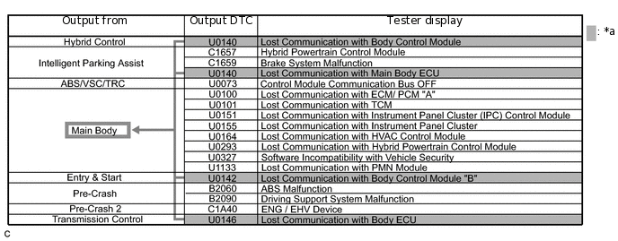
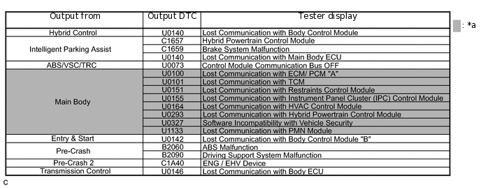
Note:This DTC table is from another model, and is only used here to show an example of DTCs that are output when there is an open in a CAN branch line for the main body ECU. This table does not show DTCs applicable to this vehicle.
Even though a DTC title may indicate a communication error with a specific ECU, the ECU name used in the DTC name on the GTS may differ depending on the ECU that stores the DTC. (Regarding output DTCs, refer to step 6 and the DTC chart for each ECU.)
Tip:As multiple ECUs indicate a communication stop with the main body ECU, the possibility of a communication stop of the main body ECU is high.
If almost all of the communication DTCs of an ECU are stored, a communication stop of the ECU is suspected.
*a
Items to be Checked
-
-
Note:This DTC table is from another model, and is only used here to show an example of DTCs that are output when there is an open in a CAN branch line for the main body ECU. This table does not show DTCs applicable to this vehicle.
Tip:If almost all of the DTCs of the main body ECU are stored, the possibility of a communication stop of the main body ECU is high.
When a CAN communication error occurs, many DTCs are output. DTCs other than communication error DTCs (such as DTCs that start with C or B) and communication DTCs for the ABS system are important DTCs, however it may be easier to determine the malfunctioning part by examining the overall situation without considering these DTCs.
To help determine the part of the sub bus that has a communication error, prioritize the communication stop DTCs stored in the gateway function equipped ECU.
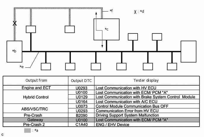
*a
Items to be Checked
*b
ECM
*c
Gateway Function Equipped ECU
*d
Location of Malfunction
*e
V Bus
*f
Sub Bus
Note:This DTC table is from another model, and is only used here to show the ECUs connected to both a V bus and a sub bus. It shows DTCs output when there is an open in the main bus lines for the ECM on the sub bus. This table does not show DTCs applicable to this vehicle.
Tip:As gateway function equipped ECUs (sub bus monitor ECU) monitor signals from all ECUs that are connected to sub buses, gateway function equipped ECUs can detect ECUs with a communication stop more accurately.
When there is a communication stop for the gateway function equipped ECU (gateway), communication with ECUs connected to other buses such as the V bus stops. Therefore, communication DTCs for ECUs connected to other buses are also stored.
When any of the following malfunctions occurs, many DTCs are likely to be output from many ECUs. Because of this, it may be difficult to determine the probable malfunctioning part.
Short between CAN lines (CANH and CANL)
Short between a CAN line (CANH or CANL) and ground
Short between a CAN line (CANH or CANL) and +B
Open in a CAN branch line (CANH or CANL) of an ECU or sensor
Open in a CAN main bus line (CANH or CANL) between 2 ECUs that have a terminating resistor
DTC TABLE BY ECU
Tip:In the CAN communication system, the CAN communication DTCs of each ECU can be displayed using the GTS.
If CAN communication system DTCs are output, the malfunction cannot be determined only by the DTCs. Perform troubleshooting according to How to Proceed with Troubleshooting.
If the system function temporarily returns to normal, DTCs may not be output again even though the following DTC check procedures are used.
ECM (for 1ND-TV) / GTS Display "Engine and ECT"
Powertrain > Engine and ECT > Trouble Codes
Tip:This ECU uses the CAN communication system for DTC communication.
*: w/ Stop and Start System
Table 4. ECM / GTS Display "Engine and ECT" DTC
Detection Item
DTC Detection Condition
DTC Detection Pre-condition
DTC Check Procedure
Warning Indication in Meter
DTC Storage Method
U0129
Lost Communication with Skid Control ECU
The ECM does not receive data from the brake actuator assembly for 2.4 seconds or more.
Both conditions are met:
The ignition switch is ON for 2.1 seconds or more.
The power source voltage of the ECM is 10.5 V or more.
Turn the ignition switch to ON and wait at least 4.5 seconds.
MIL illuminates.
DTC is stored until it is cleared using the GTS.
U1103*
Lost Communication with Stop and Start Control Module
The ECM does not receive data from the engine stop and start ECU for 1.25 seconds or more.
Both conditions are met:
The ignition switch is ON for 1 second or more.
The power source voltage of the ECM is 10.5 V or more.
Turn the ignition switch to ON and wait at least 2.25 seconds.
-
DTC is stored until it is cleared using the GTS.
TCM (for 1ND-TV and Multi-mode Manual Transaxle System) / GTS Display "Multi-Mode M/T"
Powertrain > Multi-Mode M/T > Trouble Codes
Tip:This ECU uses the CAN communication system for DTC communication.
*: Refer to Multi-mode Manual Transaxle System.
Table 5. TCM / GTS Display "Multi-Mode M/T" DTC
Detection Item
DTC Detection Condition
DTC Detection Pre-condition
DTC Check Procedure
Warning Indication in Meter
DTC Storage Method
U0100*
Lost Communication with ECM / PCM "A"
The TCM does not receive data from the ECM for 7.4 seconds or more.
Both conditions are met:
The ignition switch is ON for 0.5 seconds or more.
The power source voltage of the TCM is 10.5 V or more.
Turn the ignition switch to ON and wait at least 7.9 seconds.
MIL illuminates.
DTC is stored until it is cleared using the GTS.
ECM (for 1ZR-FAE) / GTS Display "Engine and ECT"
Powertrain > Engine and ECT > Trouble Codes
Tip:This ECU uses the CAN communication system for DTC communication.
*: This DTC is stored due to a local CAN communication error between the ECM and continuously variable lift controller assembly.
Table 6. ECM / GTS Display "Engine and ECT" DTC
Detection Item
DTC Detection Condition
DTC Detection Pre-condition
DTC Check Procedure
Warning Indication in Meter
DTC Storage Method
U0129
Lost Communication with Brake System Control Module
The ECM does not receive data from the brake actuator assembly for 2.34 seconds or more.
Both conditions are met:
The ignition switch is ON for 10 seconds or more.
The power source voltage of the ECM is 10.5 V or more.
Turn the ignition switch to ON and wait at least 12.34 seconds.
MIL illuminates.
DTC is stored until it is cleared using the GTS.
U011B*
Lost Communication with Rocker Arm Control Module "A"
The ECM does not receive data from the continuously variable valve lift controller assembly for 0.2 seconds or more.
Both conditions are met:
The ignition switch is ON for 0.05 seconds or more.
The power source voltage of the ECM is 8 V or more.
Turn the ignition switch to ON and wait at least 1 second.
MIL illuminates.
DTC is stored until it is cleared using the GTS.
ECM (for 1NR-FE, 1ZR-FE or 2ZR-FE) / GTS Display "Engine and ECT"
Tip:The ECM is connected to the CAN communication system, but the ECM does not store or output CAN communication DTCs.
ECM (for 8NR-FTS) / GTS Display "Engine"
Powertrain > Engine > Trouble Codes
Tip:This ECU uses the CAN communication system for DTC communication.
*1: Refer to SFI System.
*2: w/ Stop and Start System
*3: w/ Multi-information Display (Segment LCD type)
*4: w/ Multi-information Display (Dot LCD type, color TFT type)
The ECM incorporates the speed limiter system.
Table 7. ECM / GTS Display "Engine" DTC
Detection Item
DTC Detection Condition
DTC Detection Pre-condition
DTC Check Procedure
Warning Indication in Meter
DTC Storage Method
U010187*1
Lost Communication with TCM Missing Message
The ECM does not receive data from the TCM for 1.25 seconds or more.
Both conditions are met:
The ignition switch is ON for 1 second or more.
The power source voltage of the ECM is 10.5 V or more.
Turn the ignition switch to ON and wait at least 2.25 seconds.
MIL illuminates.
DTC is stored until it is cleared using the GTS.
U012200
Lost Communication with Vehicle Dynamics Control Module
The ECM does not receive data from the brake actuator assembly for 2.34 seconds or more.
Both conditions are met:
The ignition switch is ON for 1 second or more.
The power source voltage of the ECM is 10.5 V or more.
Turn the ignition switch to ON and wait at least 3.34 seconds.
Adjustable speed limiter indicator (amber) illuminates.*3
Displays messages on the multi-information display.*4
DTC is stored until it is cleared using the GTS.
U012587
Lost Communication with Multi-axis Acceleration Sensor Module Missing Message
The ECM does not receive data from the airbag sensor assembly for 1 second or more.
Both conditions are met:
The ignition switch is ON for 1 second or more.
The power source voltage of the ECM is 10.5 V or more.
Turn the ignition switch to ON and wait at least 2 seconds.
-
DTC is stored until it is cleared using the GTS.
U012987
Lost Communication with Brake System Control Module Missing Message
The ECM does not receive data from the brake actuator assembly for 2.34 seconds or more.
Both conditions are met:
The ignition switch is ON for 2 seconds or more.
The power source voltage of the ECM is 10.5 V or more.
Turn the ignition switch to ON and wait at least 4.34 seconds.
MIL illuminates.
DTC is stored until it is cleared using the GTS.
U110387*2
Lost Communication with Stop and Start Control Module
The ECM does not receive data from the engine stop and start ECU for 1.16 seconds or more.
Both conditions are met:
The ignition switch is ON for 1 second or more.
The power source voltage of the ECM is 10.5 V or more.
Turn the ignition switch to ON and wait at least 2.16 seconds.
-
DTC is stored until it is cleared using the GTS.
TCM (for 8NR-FTS and Manual Transaxle System) / GTS Display "Transmission"
Powertrain > Transmission > Trouble Codes
Tip:This ECU uses the CAN communication system for DTC communication.
*: Refer to Manual Transaxle System.
Table 8. TCM / GTS Display "Transmission" DTC
Detection Item
DTC Detection Condition
DTC Detection Pre-condition
DTC Check Procedure
Warning Indication in Meter
DTC Storage Method
U010087*
Lost Communication with TCM Missing Message
The TCM does not receive data from the ECM for 1.25 seconds or more.
Both conditions are met:
The ignition switch is ON for 1 second or more.
The power source voltage of the ECM is 10.5 V or more.
Turn the ignition switch to ON and wait at least 2.25 seconds.
-
DTC is stored until it is cleared using the GTS.
TCM (for 8NR-FTS and Continuously Variable Transaxle System) / GTS Display "Transmission"
Powertrain > Transmission > Trouble Codes
Tip:This ECU uses the CAN communication system for DTC communication.
*: Refer to Continuously Variable Transaxle System.
Table 9. TCM / GTS Display "Transmission" DTC
Detection Item
DTC Detection Condition
DTC Detection Pre-condition
DTC Check Procedure
Warning Indication in Meter
DTC Storage Method
U010087*
Lost Communication with TCM Missing Message
The TCM does not receive data from the ECM for 1.25 seconds or more.
Both conditions are met:
The ignition switch is ON for 1 second or more.
The power source voltage of the ECM is 10.5 V or more.
Turn the ignition switch to ON and wait at least 2.25 seconds.
MIL illuminates.
DTC is stored until it is cleared using the GTS.
ECM (for 8NR-FTS) / GTS Display "Cruise Control"
Powertrain > Cruise Control > Trouble Codes
Tip:This ECU uses the CAN communication system for DTC communication.
Table 10. ECM / GTS Display "Cruise Control" DTC
Detection Item
DTC Detection Condition
DTC Detection Pre-condition
DTC Check Procedure
Warning Indication in Meter
DTC Storage Method
U012287
Lost Communication with Vehicle Dynamics Control Module Missing Message
The ECM does not receive data from the brake actuator assembly for 2.58 seconds or more.
All conditions are met:
The ignition switch is ON for 2.1 seconds or more.
The power source voltage of the ECM is 10.5 V or more.
The radar cruise control system (vehicle control mode) is operating.
Allow the radar cruise control system (vehicle control mode) to operate for 4.68 seconds or more.
Displays messages on the multi-information display.
DTC is stored until it is cleared using the GTS.
ECM (for 1WW) / GTS Display "Engine and ECT"
Powertrain > Engine and ECT > Trouble Codes
Tip:This ECU uses the CAN communication system for DTC communication.
*: Refer to ECD System.
Table 11. ECM / GTS Display "Engine and ECT" DTC
Detection Item
DTC Detection Condition
Warning Indication in Meter
DTC Storage Method
U0028
Vehicle Communication Bus "A"
Communication malfunction.
(3 trip detection logic)
-
DTC is stored until it is cleared using the GTS.
U0129
Lost Communication with Brake System Control Module
No communication between ECM and skid control ECU.
(1 trip detection logic)
MIL illuminates.
DTC is stored until it is cleared using the GTS.
U0307*
Software Incompatibility With Glow Plug Control Module 1
Incorrect glow plug controller assembly installed.
(3 trip detection logic)
-
DTC is stored until it is cleared using the GTS.
U1500*
OMI Not Initialized
OMI (Oil Maintenance Interval) initialization is not performed.
(1 trip detection logic)
-
DTC is stored until it is cleared using the GTS.
Brake Actuator Assembly (w/o VSC) / GTS Display "ABS/VSC/TRC"
Chassis > ABS/VSC/TRC > Trouble Codes
Tip:This ECU uses the CAN communication system for DTC communication.
Table 12. Brake Actuator Assembly / GTS Display "ABS/VSC/TRC" DTC
Detection Item
DTC Detection Condition
DTC Detection Pre-condition
DTC Check Procedure
Warning Indication in Meter
DTC Storage Method
U0073
Control Module Communication Bus OFF
Bus off is judged for 0.1 seconds or more.
Both conditions are met:
The ignition switch is ON for 1 second or more.
The power source voltage of the brake actuator assembly (+BS terminal voltage) is between 9.6 and 16.5 V.
Turn the ignition switch to ON and check that the initial light check illumination turns off, and then wait at least 3 seconds.
ABS warning light illuminates.
Brake warning light illuminates.
DTC is stored until it is cleared using the GTS.
Brake Actuator Assembly (w/ VSC) / GTS Display "ABS/VSC/TRC"
Chassis > ABS/VSC/TRC > Trouble Codes
Tip:This ECU uses the CAN communication system for DTC communication.
Table 13. Brake Actuator Assembly / GTS Display "ABS/VSC/TRC" DTC
Detection Item
DTC Detection Condition
DTC Detection Pre-condition
DTC Check Procedure
Warning Indication in Meter
DTC Storage Method
U0073
Control Module Communication Bus OFF
Bus off is judged for 0.1 seconds or more.
Both conditions are met:
The ignition switch is ON for 1 second or more.
The power source voltage (+BS terminal voltage) of the brake actuator assembly is between 9.6 and 16.5 V.
Turn the ignition switch to ON and check that the initial light check illumination turns off, and then wait at least 3 seconds.
ABS warning light illuminates.
Brake warning light illuminates.
Slip warning light illuminates.
DTC is stored until it is cleared using the GTS.
U0100
Lost Communication with ECM/PCM
The brake actuator assembly does not receive data from the ECM for 2.5 seconds or more.
All conditions are met:
Vehicle speed is 6 km/h (4 mph) or more.
The ignition switch is ON for 1 second or more.
The power source voltage (+BS terminal voltage) of the brake actuator assembly is between 9.6 and 16.5 V.
Turn the ignition switch to ON and drive the vehicle at a speed of 6 km/h (4 mph) or more for 6 seconds or more. Check that the warning light remains off after turning off following the initial light check.
Slip warning light illuminates.
DTC is stored until it is cleared using the GTS.
U0123
Lost Communication with Yaw Rate Sensor Module
The brake actuator assembly does not receive data from the airbag sensor assembly for 1.1 seconds or more.
All conditions are met:
Vehicle speed is 6 km/h (4 mph) or more.
The ignition switch is ON for 1 second or more.
The power source voltage (+BS terminal voltage) of the brake actuator assembly is between 9.6 and 16.5 V.
Turn the ignition switch to ON and drive the vehicle at a speed of 6 km/h (4 mph) or more for 3 seconds or more. Check that the warning light remains off after turning off following the initial light check.
Slip warning light illuminates.
DTC is stored until it is cleared using the GTS.
U0126
Lost Communication with Steering Angle Sensor Module
The brake actuator assembly does not receive data from the steering sensor (spiral cable with sensor sub-assembly) for 1.1 seconds or more.
All conditions are met:
Vehicle speed is 6 km/h (4 mph) or more.
The ignition switch is ON for 1 second or more.
The power source voltage (+BS terminal voltage) of the brake actuator assembly is between 9.6 and 16.5 V.
Turn the ignition switch to ON and drive the vehicle at a speed of 6 km/h (4 mph) or more for 3 seconds or more. Check that the warning light remains off after turning off following the initial light check.
Slip warning light illuminates.
DTC is stored until it is cleared using the GTS.
Main Body ECU (Multiplex Network Body ECU) / GTS Display "Main Body"
Body Electrical > Main Body > Trouble Codes
Tip:This ECU uses the CAN communication system for DTC communication.
*1: w/ Entry and Start System
*2: w/ Toyota Safety Sense
Table 14. Main Body ECU (Multiplex Network Body ECU) / GTS Display "Main Body" DTC
Detection Item
DTC Detection Condition
DTC Detection Pre-condition
DTC Check Procedure
Warning Indication in Meter
DTC Storage Method
U0100
Lost Communication With ECM/PCM "A"
The main body ECU (multiplex network body ECU) does not receive data from the ECM for 10 seconds or more.
Both conditions are met:
Power source status change (+B OFF → ON, ACC ON ←→ OFF, IG ON ←→ OFF) is detected and 10 seconds or more elapse.
The power source voltage of the main body ECU (multiplex network body ECU) is 10 V or more.
Turn the ignition switch to ON and wait at least 20 seconds.
-
DTC is stored until it is cleared using the GTS.
U0101
Lost Communication with ECT
The main body ECU (multiplex network body ECU) does not receive data from the ECM for 10 seconds or more.
Both conditions are met:
Power source status change (+B OFF → ON, ACC ON ←→ OFF, IG ON ←→ OFF) is detected and 10 seconds or more elapse.
The power source voltage of the main body ECU (multiplex network body ECU) is 10 V or more.
Turn the ignition switch to ON and wait at least 20 seconds.
-
DTC is stored until it is cleared using the GTS.
U0120*1
Lost Communication With Starter / Generator Control Module
The main body ECU (multiplex network body ECU) does not receive data from the certification ECU (smart key ECU assembly) for 10 seconds or more.
Both conditions are met:
Power source status change (+B OFF → ON, ACC ON ←→ OFF, IG ON ←→ OFF) is detected and 10 seconds or more elapse.
The power source voltage of the main body ECU (multiplex network body ECU) is 10 V or more.
Turn the ignition switch to ON and wait at least 20 seconds.
-
DTC is stored until it is cleared using the GTS.
U0151
Lost Communication with Airbag ECU
The main body ECU (multiplex network body ECU) does not receive data from the airbag sensor assembly for 10 seconds or more.
Both conditions are met:
Power source status change (+B OFF → ON, ACC ON ←→ OFF, IG ON ←→ OFF) is detected and 10 seconds or more elapse.
The power source voltage of the main body ECU (multiplex network body ECU) is 10 V or more.
Turn the ignition switch to ON and wait at least 20 seconds.
-
DTC is stored until it is cleared using the GTS.
U0155
Lost Communication with Combination Meter
The main body ECU (multiplex network body ECU) does not receive data from the combination meter assembly for 10 seconds or more.
Both conditions are met:
Power source status change (+B OFF → ON, ACC ON ←→ OFF, IG ON ←→ OFF) is detected and 10 seconds or more elapse.
The power source voltage of the main body ECU (multiplex network body ECU) is 10 V or more.
Turn the ignition switch to ON and wait at least 20 seconds.
-
DTC is stored until it is cleared using the GTS.
U0164
Communication Error from A/C
The main body ECU (multiplex network body ECU) does not receive data from the air conditioning amplifier assembly for 10 seconds or more.
Both conditions are met:
Power source status change (+B OFF → ON, ACC ON ←→ OFF, IG ON ←→ OFF) is detected and 10 seconds or more elapse.
The power source voltage of the main body ECU (multiplex network body ECU) is 10 V or more.
Turn the ignition switch to ON and wait at least 20 seconds.
-
DTC is stored until it is cleared using the GTS.
U023A*2
Lost Communication with Front Camera Module
The main body ECU (multiplex network body ECU) does not receive data from the pre-crash safety city sensor for 10 seconds or more.
Both conditions are met:
Power source status change (+B OFF → ON, ACC ON ←→ OFF, IG ON ←→ OFF) is detected and 10 seconds or more elapse.
The power source voltage of the main body ECU (multiplex network body ECU) is 10 V or more.
Turn the ignition switch to ON and wait at least 20 seconds.
-
DTC is stored until it is cleared using the GTS.
U0327*1
Software Incompatibility with Vehicle Security Control Module
The main body ECU (multiplex network body ECU) does not receive data from the certification ECU (smart key ECU assembly) for 10 seconds or more.
Both conditions are met:
Power source status change (+B OFF → ON, ACC ON ←→ OFF, IG ON ←→ OFF) is detected and 10 seconds or more elapse.
The power source voltage of the main body ECU (multiplex network body ECU) is 10 V or more.
Turn the ignition switch to ON and wait at least 20 seconds.
-
DTC is stored until it is cleared using the GTS.
Combination Meter Assembly / GTS Display "Combination Meter"
Body Electrical > Combination Meter > Trouble Codes
Tip:This ECU uses the CAN communication system for DTC communication.
*: for Multi-information Display (Segment LCD Type)
Table 15. Combination Meter Assembly / GTS Display "Combination Meter" DTC
Detection Item
DTC Detection Condition
DTC Detection Pre-condition
DTC Check Procedure
Warning Indication in Meter
DTC Storage Method
U0100
Lost Communication with ECM/PCM "A"
The combination meter assembly does not receive data from the ECM for 2 seconds or more.
Both conditions are met:
The ignition switch is ON.
The power source voltage of the combination meter assembly is 9.5 V or more.
Turn the ignition switch to ON and wait at least 2 seconds.
-
DTC is stored until it is cleared using the GTS.
U0129
Lost Communication with Skid Control ECU
The combination meter assembly does not receive data from the brake actuator assembly for 3 seconds or more.
Both conditions are met:
The ignition switch is ON.
The power source voltage of the combination meter assembly is 9.5 V or more.
Turn the ignition switch to ON and wait at least 3 seconds.
-
DTC is stored until it is cleared using the GTS.
U0131
Lost Communication with Power Steering Control Module
The combination meter assembly does not receive data from the power steering ECU assembly for 3 seconds or more.
Both conditions are met:
The ignition switch is ON.
The power source voltage of the combination meter assembly is 9.5 V or more.
Turn the ignition switch to ON and wait at least 3 seconds.
EPS warning light illuminates.
DTC is stored until it is cleared using the GTS.
U0142*
Lost Communication with Body Control Module "B"
The combination meter assembly does not receive data from the main body ECU (multiplex network body ECU) for 3 seconds or more.
Both conditions are met:
The ignition switch is ON.
The power source voltage of the combination meter assembly is 9.5 V or more.
Turn the ignition switch to ON and wait at least 3 seconds.
-
DTC is stored until it is cleared using the GTS.
U0151
Lost Communication with Airbag ECU
The combination meter assembly does not receive data from the airbag sensor assembly for 10 seconds or more.
Both conditions are met:
The ignition switch is ON.
The power source voltage of the combination meter assembly is 9.5 V or more.
Turn the ignition switch to ON and wait at least 10 seconds.
SRS warning light illuminates.
DTC is stored until it is cleared using the GTS.
U0163
Lost Communication With Navigation Control Module
The combination meter assembly does not receive data from the radio and display receiver assembly for 3 seconds or more.
Both conditions are met:
The ignition switch is ON.
The power source voltage of the combination meter assembly is 9.5 V or more.
Turn the ignition switch to ON and wait at least 3 seconds.
-
DTC is stored until it is cleared using the GTS.
U023A
Lost Communication with Front Camera Module
The combination meter assembly does not receive data from the pre-crash safety city sensor for 10 seconds or more.
Both conditions are met:
The ignition switch is ON.
The power source voltage of the combination meter assembly is 9.5 V or more.
Turn the ignition switch to ON and wait at least 10 seconds.
-
DTC is stored until it is cleared using the GTS.
Steering Sensor (Spiral Cable with Sensor Sub-assembly) (w/ VSC) / GTS Display "-"
Tip:The steering sensor (spiral cable with sensor sub-assembly) is connected to the CAN communication system, but the steering sensor (spiral cable with sensor sub-assembly) does not store or output CAN communication DTCs.
Airbag Sensor Assembly / GTS Display "Airbag"
Tip:The airbag sensor assembly is connected to the CAN communication system, but the airbag sensor assembly does not store or output CAN communication DTCs.
Air Conditioning Amplifier Assembly (w/ Air Conditioning System) / GTS Display "Air Conditioner"
Body Electrical > Air Conditioner > Trouble Codes
Tip:This ECU uses the CAN communication system for DTC communication.
Table 16. Air Conditioning Amplifier Assembly / GTS Display "Air Conditioner" DTC
Detection Item
DTC Detection Condition
DTC Detection Pre-condition
DTC Check Procedure
Warning Indication in Meter
DTC Storage Method
U0100
Lost Communication with ECM
The air conditioning amplifier assembly does not receive data from the ECM for 5 seconds or more.
Both conditions are met:
The ignition switch is ON.
The power source voltage of the air conditioning amplifier assembly is 10 V or more.
Turn the ignition switch to ON and wait at least 5 seconds.
-
DTC is stored until it is cleared using the GTS.
U0131
Lost Communication with Electric Power Steering ECU
The air conditioning amplifier assembly does not receive data from the power steering ECU assembly for 5 seconds or more.
Both conditions are met:
The ignition switch is ON.
The power source voltage of the air conditioning amplifier assembly is 10 V or more.
Turn the ignition switch to ON and wait at least 5 seconds.
-
DTC is stored until it is cleared using the GTS.
U0142
Lost Communication with Main Body ECU
The air conditioning amplifier assembly does not receive data from the main body ECU (multiplex network body ECU) for 5 seconds or more.
Both conditions are met:
The ignition switch is ON.
The power source voltage of the air conditioning amplifier assembly is 10 V or more.
Turn the ignition switch to ON and wait at least 5 seconds.
-
DTC is stored until it is cleared using the GTS.
U0155
Lost Communication with Combination Meter
The air conditioning amplifier assembly does not receive data from the combination meter assembly for 5 seconds or more.
Both conditions are met:
The ignition switch is ON.
The power source voltage of the air conditioning amplifier assembly is 10 V or more.
Turn the ignition switch to ON and wait at least 5 seconds.
-
DTC is stored until it is cleared using the GTS.
Power Steering ECU Assembly / GTS Display "EMPS"
Chassis > EMPS > Trouble Codes
Tip:This ECU uses the CAN communication system for DTC communication.
Table 17. Power Steering ECU Assembly / GTS Display "EMPS" DTC
Detection Item
DTC Detection Condition
DTC Detection Pre-condition
DTC Check Procedure
Warning Indication in Meter
DTC Storage Method
U0100
Lost Communication with ECM/PCM "A"
The power steering ECU assembly does not receive data from the ECM for 300 seconds or more.
All conditions are met:
The ignition switch is ON for 3 seconds or more.
The power source voltage of the power steering ECU assembly is 9 V or more.
Vehicle speed is 20 km/h (12 mph) or more.
Drive the vehicle for 303 seconds at a speed of 20 km/h (12 mph) or more.
EPS warning light illuminates.
DTC remains stored only while malfunction is occurring.
U0129
Lost Communication with Brake System Control Module
The power steering ECU assembly does not receive data from the brake actuator assembly for 2.34 seconds or more.
Both conditions are met:
The ignition switch is ON for 3 seconds or more.
The power source voltage of the power steering ECU assembly is 9 V or more.
Turn the ignition switch to ON and wait at least 5.34 seconds.
EPS warning light illuminates.
DTC remains stored only while malfunction is occurring.
U1110
Lost Communication with Clearance Sonar Module
The power steering ECU assembly does not receive data from the clearance warning ECU assembly for 1.34 seconds or more.
Both conditions are met:
The ignition switch is ON for 3 seconds or more.
The power source voltage of the power steering ECU assembly is 9 V or more.
Turn the ignition switch to ON and wait at least 4.34 seconds.
-
DTC remains stored only while malfunction is occurring.
Certification ECU (Smart Key ECU Assembly) (w/ Entry and Start System) / GTS Display "Entry&Start"
Body Electrical > Entry&Start > Trouble Codes
Tip:This ECU uses the CAN communication system for DTC communication.
*: w/ Stop and Start System
Table 18. Certification ECU (Smart Key ECU Assembly) / GTS Display "Entry&Start" DTC
Detection Item
DTC Detection Condition
DTC Detection Pre-condition
DTC Check Procedure
Warning Indication in Meter
DTC Storage Method
U0100
Lost Communication with ECM/PCM
The certification ECU (smart key ECU assembly) does not receive data from the ECM for 10 seconds or more.
Both conditions are met:
The ignition switch is ON for 10 seconds or more.
The power source voltage of the certification ECU (smart key ECU assembly) is 10 V or more.
Turn the ignition switch to ON and wait at least 20 seconds.
-
DTC is stored until it is cleared using the GTS.
U0142
Lost Communication with Main Body ECU
The certification ECU (smart key ECU assembly) does not receive data from the main body ECU (multiplex network body ECU) for 10 seconds or more.
Both conditions are met:
The ignition switch is ON for 10 seconds or more.
The power source voltage of the certification ECU (smart key ECU assembly) is 10 V or more.
Turn the ignition switch to ON and wait at least 20 seconds.
-
DTC is stored until it is cleared using the GTS.
U0155
Lost Communication with Combination Meter
The certification ECU (smart key ECU assembly) does not receive data from the combination meter assembly for 10 seconds or more.
Both conditions are met:
The ignition switch is ON for 10 seconds or more.
The power source voltage of the certification ECU (smart key ECU assembly) is 10 V or more.
Turn the ignition switch to ON and wait at least 20 seconds.
-
DTC is stored until it is cleared using the GTS.
U1103*
Lost Communication with Stop and Start Control Module
The certification ECU (smart key ECU assembly) does not receive data from the engine stop and start ECU for 10 seconds or more.
Both conditions are met:
The ignition switch is ON for 10 seconds or more.
The power source voltage of the certification ECU (smart key ECU assembly) is 10 V or more.
Turn the ignition switch to ON and wait at least 20 seconds.
-
DTC is stored until it is cleared using the GTS.
Certification ECU (Smart Key ECU Assembly) (w/ Entry and Start System) / GTS Display "Power Source Control"
Body Electrical > Power Source Control > Trouble Codes
Tip:This ECU uses the CAN communication system for DTC communication.
*: w/ Stop and Start System
Table 19. Certification ECU (Smart Key ECU Assembly) / GTS Display "Power Source Control" DTC
Detection Item
DTC Detection Condition
DTC Detection Pre-condition
DTC Check Procedure
Warning Indication in Meter
DTC Storage Method
U0100
Lost Communication with ECM / PCM
The certification ECU (smart key ECU assembly) does not receive data from the ECM for 10 seconds or more.
Both conditions are met:
The ignition switch is ON for 10 seconds or more.
The power source voltage of the certification ECU (smart key ECU assembly) is 10 V or more.
Turn the ignition switch to ON and wait at least 20 seconds.
-
DTC is stored until it is cleared using the GTS.
U0140
Lost Communication with Main Body ECU
The certification ECU (smart key ECU assembly) does not receive data from the main body ECU (multiplex network body ECU) for 10 seconds or more.
Both conditions are met:
The ignition switch is ON for 10 seconds or more.
The power source voltage of the certification ECU (smart key ECU assembly) is 10 V or more.
Turn the ignition switch to ON and wait at least 20 seconds.
-
DTC is stored until it is cleared using the GTS.
U0155
Lost Communication with Combination Meter
The certification ECU (smart key ECU assembly) does not receive data from the combination meter assembly for 10 seconds or more.
Both conditions are met:
The ignition switch is ON for 10 seconds or more.
The power source voltage of the certification ECU (smart key ECU assembly) is 10 V or more.
Turn the ignition switch to ON and wait at least 20 seconds.
-
DTC is stored until it is cleared using the GTS.
U1103*
Lost Communication with Stop and Start Control Module
The certification ECU (smart key ECU assembly) does not receive data from the engine stop and start ECU for 10 seconds or more.
Both conditions are met:
The ignition switch is ON for 10 seconds or more.
The power source voltage of the certification ECU (smart key ECU assembly) is 10 V or more.
Turn the ignition switch to ON and wait at least 20 seconds.
-
DTC is stored until it is cleared using the GTS.
Radio and Display Receiver Assembly (for Radio and Display Type) / GTS Display "Navigation System"
Body Electrical > Navigation System > Trouble Codes
Tip:This ECU uses the CAN communication system for DTC communication.
Table 20. Radio and Display Receiver Assembly / GTS Display "Navigation System" DTC
Detection Item
DTC Detection Condition
DTC Detection Pre-condition
DTC Check Procedure
Warning Indication in Meter
DTC Storage Method
U0073
Sending Malfunction (Navigation to APGS)
The radio and display receiver assembly does not send/receive data 10 times in succession.
Both conditions are met:
The ignition switch is ACC for 1 second or more.
The power source voltage of the radio and display receiver assembly is 9.5 V or more.
Turn the ignition switch to ACC and wait at least 11 seconds.
-
DTC is stored until it is cleared using the GTS.
U0100
Engine ECU Communication
The radio and display receiver assembly does not receive data from the ECM for 10 seconds or more.
Both conditions are met:
The ignition switch is ON for 1 second or more.
The power source voltage of the radio and display receiver assembly is 9.5 V or more.
Turn the ignition switch to ON and wait at least 11 seconds.
-
DTC is stored until it is cleared using the GTS.
U0129
VSC (ECB) ECU Communication
The radio and display receiver assembly does not receive data from the brake actuator assembly for 1 second or more.
Both conditions are met:
The ignition switch is ON for 1 second or more.
The power source voltage of the radio and display receiver assembly is 9.5 V or more.
Turn the ignition switch to ON and wait at least 2 seconds.
-
DTC is stored until it is cleared using the GTS.
U0140
Lost Communication with Body Control Module
The radio and display receiver assembly does not receive data from the main body ECU (multiplex network body ECU) for 3 seconds or more.
Both conditions are met:
The ignition switch is ON for 1 second or more.
The power source voltage of the radio and display receiver assembly is 9.5 V or more.
Turn the ignition switch to ON and wait at least 4 seconds.
-
DTC is stored until it is cleared using the GTS.
U0155
Meter ECU Communication
The radio and display receiver assembly does not receive data from the combination meter assembly for 30 seconds or more.
Both conditions are met:
The ignition switch is ON for 1 second or more.
The power source voltage of the radio and display receiver assembly is 9.5 V or more.
Turn the ignition switch to ON and wait at least 31 seconds.
-
DTC is stored until it is cleared using the GTS.
U0164
Air Conditioner ECU Communication
The radio and display receiver assembly does not receive data from the air conditioning amplifier assembly for 15 seconds or more.
Both conditions are met:
The ignition switch is ON.
The power source voltage of the radio and display receiver assembly is 9.5 V or more.
Turn the ignition switch to ON and wait at least 15 seconds.
-
DTC is stored until it is cleared using the GTS.
Clearance Warning ECU Assembly (w/ Simple Intelligent Parking Assist System) / GTS Display "Clearance Sonar / Simple-IPA."
Body Electrical > Clearance Sonar / Simple-IPA. > Trouble Codes
Tip:This ECU uses the CAN communication system for DTC communication.
*1: Refer to Simple Intelligent Parking Assist System
*2: w/ Stop and Start System
Table 21. Clearance Warning ECU Assembly / GTS Display "Clearance Sonar / Simple-IPA." DTC
Detection Item
DTC Detection Condition
DTC Detection Pre-condition
DTC Check Procedure
Warning Indication in Meter
DTC Storage Method
U0073
Control Module Communication Bus "A" Off
The clearance warning ECU assembly detects bus-off or register freeze.
Both conditions are met:
The ignition switch is ON for 5 seconds or more.
The power source voltage of the clearance warning ECU assembly is 10.2 V or more.
Turn the ignition switch to ON and wait at least 10.05 seconds.
-
DTC is stored until it is cleared using the GTS.
U0100
Lost Communication with ECM/PCM "A"
The clearance warning ECU assembly does not receive data from the ECM for 3.5 seconds or more.
Both conditions are met:
The ignition switch is ON for 5 seconds or more.
The power source voltage of the clearance warning ECU assembly is 10.2 V or more.
Turn the ignition switch to ON and wait at least 8.5 seconds.
-
DTC is stored until it is cleared using the GTS.
U0101
Lost Communication with TCM
The clearance warning ECU assembly does not receive data from the TCM for 5 seconds or more.
Both conditions are met:
The ignition switch is ON for 5 seconds or more.
The power source voltage of the clearance warning ECU assembly is 10.2 V or more.
Turn the ignition switch to ON and wait at least 10 seconds.
-
DTC is stored until it is cleared using the GTS.
U0126
Lost Communication with Steering Angle Sensor Module
The clearance warning ECU assembly does not receive data from the steering sensor (spiral cable with sensor sub-assembly) for 11.2 seconds or more.
Both conditions are met:
The ignition switch is ON for 5 seconds or more.
The power source voltage of the clearance warning ECU assembly is 10.2 V or more.
Turn the ignition switch to ON and wait at least 16.2 seconds.
-
DTC is stored until it is cleared using the GTS.
U0129
Lost Communication with Brake System Control Module
The clearance warning ECU assembly does not receive data from the brake actuator assembly for 5.1 seconds or more.
Both conditions are met:
The ignition switch is ON for 5 seconds or more.
The power source voltage of the clearance warning ECU assembly is 10.2 V or more.
Turn the ignition switch to ON and wait at least 10.1 seconds.
-
DTC is stored until it is cleared using the GTS.
U0131
Lost Communication with Power Steering Control Module
The clearance warning ECU assembly does not receive data from the power steering ECU assembly for 1.4 seconds or more.
Both conditions are met:
The ignition switch is ON for 5 seconds or more.
The power source voltage of the clearance warning ECU assembly is 10.2 V or more.
Turn the ignition switch to ON and wait at least 6.4 seconds.
-
DTC is stored until it is cleared using the GTS.
U0142
Lost Communication with Body Control Module "B"
The clearance warning ECU assembly does not receive data from the main body ECU (multiplex network body ECU) for 11 seconds or more.
Both conditions are met:
The ignition switch is ON for 5 seconds or more.
The power source voltage of the clearance warning ECU assembly is 10.2 V or more.
Turn the ignition switch to ON and wait at least 16 seconds.
-
DTC is stored until it is cleared using the GTS.
U0151
Lost Communication with Restraints Control Module
The clearance warning ECU assembly does not receive data from the airbag sensor assembly for 1.2 seconds or more.
Both conditions are met:
The ignition switch is ON for 5 seconds or more.
The power source voltage of the clearance warning ECU assembly is 10.2 V or more.
Turn the ignition switch to ON and wait at least 6.2 seconds.
-
DTC is stored until it is cleared using the GTS.
U0155
Lost Communication with Combination Meter
The clearance warning ECU assembly does not receive data from the combination meter assembly for 11 seconds or more.
Both conditions are met:
The ignition switch is ON for 5 seconds or more.
The power source voltage of the clearance warning ECU assembly is 10.2 V or more.
Turn the ignition switch to ON and wait at least 16 seconds.
-
DTC is stored until it is cleared using the GTS.
U0164
Lost Communication with HVAC Control Module
The clearance warning ECU assembly does not receive data from the air conditioning amplifier assembly for 11 seconds or more.
Both conditions are met:
The ignition switch is ON for 5 seconds or more.
The power source voltage of the clearance warning ECU assembly is 10.2 V or more.
Turn the ignition switch to ON and wait at least 16 seconds.
-
DTC is stored until it is cleared using the GTS.
U0301*1
Software Incompatibility with ECM/PCM
Storage information on the clearance warning ECU assembly and data sent from ECM/PCM is different.
Both conditions are met:
The ignition switch is ON for 5 seconds or more.
The power source voltage of the clearance warning ECU assembly is 10.2 V or more.
Turn the ignition switch to ON and wait at least 6 seconds.
-
DTC is stored until ECU information becomes the same as send data from ECM/PCM.
U0322*1
Software Incompatibility with Body Control Module
Storage information on the clearance warning ECU assembly and data sent from body control module is different.
Both conditions are met:
The ignition switch is ON for 5 seconds or more.
The power source voltage of the clearance warning ECU assembly is 10.2 V or more.
Turn the ignition switch to ON and wait at least 8 seconds.
-
DTC is stored until ECU information becomes the same as send data from main body ECU (multiplex network body ECU).
U1103*2
Lost Communication with Stop and Start Control Module
The clearance warning ECU assembly does not receive data from the engine stop and start ECU assembly for 1.2 seconds or more.
Both conditions are met:
The ignition switch is ON for 5 seconds or more.
The power source voltage of the clearance warning ECU assembly is 10.2 V or more.
Turn the ignition switch to ON and wait at least 6.2 seconds.
-
DTC is stored until it is cleared using the GTS.
Headlight Swivel ECU Assembly (except Sedan with Automatic Headlight Beam Level Control System) / GTS Display "AFS"
Body Electrical > AFS > Trouble Codes
Tip:This ECU uses the CAN communication system for DTC communication.
*: Refer to Automatic Headlight Beam Level Control System
Table 22. Headlight Swivel ECU Assembly / GTS Display "AFS" DTC
Detection Item
DTC Detection Condition
DTC Detection Pre-condition
DTC Check Procedure
Warning Indication in Meter
DTC Storage Method
U0073
Control Module Communication Bus Off
The headlight swivel ECU assembly does not send/receive data 10 times in succession.
Both conditions are met:
The ignition switch is ON for 3 seconds or more.
The power source voltage of the headlight swivel ECU assembly is 10 V or more.
Turn the ignition switch to ON and wait at least 13 seconds.
-
DTC is stored until it is cleared using the GTS.
U0100
Lost Communication with ECM
The headlight swivel ECU assembly does not receive data from the ECM for 10 seconds or more.
Both conditions are met:
The ignition switch is ON for 3 seconds or more.
The power source voltage of the headlight swivel ECU assembly is 10 V or more.
Turn the ignition switch to ON and wait at least 13 seconds.
AFS OFF indicator light flashes.
DTC is stored until it is cleared using the GTS.
U0129
Lost Communication with Skid Control ECU
The headlight swivel ECU assembly does not receive data from the brake actuator assembly for 5 seconds or more.
Both conditions are met:
The ignition switch is ON for 3 seconds or more.
The power source voltage of the headlight swivel ECU assembly is 10 V or more.
Turn the ignition switch to ON and wait at least 8 seconds.
AFS OFF indicator light flashes.
DTC is stored until it is cleared using the GTS.
U0142
Lost Communication with Main Body ECU
The headlight swivel ECU assembly does not receive data from the main body ECU (multiplex network body ECU) for 10 seconds or more.
Both conditions are met:
The ignition switch is ON for 3 seconds or more.
The power source voltage of the headlight swivel ECU assembly is 10 V or more.
Turn the ignition switch to ON and wait at least 13 seconds.
AFS OFF indicator light flashes.
DTC is stored until it is cleared using the GTS.
U1000*
CAN Communication Failure(Message Registry)
The headlight swivel ECU assembly does not send/receive data 10 times in succession.
Both conditions are met:
The ignition switch is ON for 3 seconds or more.
The power source voltage of the headlight swivel ECU assembly is 10 V or more.
Turn the ignition switch to ON and wait at least 13 seconds.
-
DTC is stored until it is cleared using the GTS.
Headlight Leveling ECU Assembly (for Sedan with Automatic Headlight Beam Level Control System) / GTS Display "HL AutoLeveling"
Body Electrical > HL AutoLeveling > Trouble Codes
Tip:This ECU uses the CAN communication system for DTC communication.
*: Refer to Automatic Headlight Beam Level Control System
Table 23. Headlight Leveling ECU Assembly / GTS Display "HL AutoLeveling" DTC
Detection Item
DTC Detection Condition
DTC Detection Pre-condition
DTC Check Procedure
Warning Indication in Meter
DTC Storage Method
U0100
Lost Communication with ECM / PCM "A"
The headlight leveling ECU assembly does not receive data from the ECM for 10 seconds or more.
Both conditions are met:
The ignition switch is ON for 1 second or more.
The power source voltage of the headlight leveling ECU assembly is 9.5 V or more.
Turn the ignition switch to ON and wait at least 11 seconds.
-
DTC is stored until it is cleared using the GTS.
U0129
Lost Communication with Brake System Control Module
The headlight leveling ECU assembly does not receive data from the brake actuator assembly for 10 seconds or more.
Both conditions are met:
The ignition switch is ON for 1 second or more.
The power source voltage of the headlight leveling ECU assembly is 9.5 V or more.
Turn the ignition switch to ON and wait at least 11 seconds.
-
DTC is stored until it is cleared using the GTS.
U0142
Lost Communication with Body Control Module "B"
The headlight leveling ECU assembly does not receive data from the main body ECU (multiplex network body ECU) for 10 seconds or more.
Both conditions are met:
The ignition switch is ON for 1 second or more.
The power source voltage of the headlight leveling ECU assembly is 9.5 V or more.
Turn the ignition switch to ON and wait at least 11 seconds.
-
DTC is stored until it is cleared using the GTS.
U1000*
CAN Communication Failure(Message Registry)
The headlight leveling ECU assembly does not send/receive data 10 times in succession.
Both conditions are met:
The ignition switch is ON for 3 seconds or more.
The power source voltage of the headlight leveling ECU assembly is 10 V or more.
Turn the ignition switch to ON and wait at least 13 seconds.
-
DTC is stored until it is cleared using the GTS.
Engine Stop and Start ECU (w/ Stop and Start System) / GTS Display "Stop and Start"
Powertrain > Stop and Start > Trouble Codes
Tip:This ECU uses the CAN communication system for DTC communication.
*: w/ Simple Intelligent Parking Assist System
Table 24. Engine Stop and Start ECU / GTS Display "Stop and Start" DTC
Detection Item
DTC Detection Condition
DTC Detection Pre-condition
DTC Check Procedure
Warning Indication in Meter
DTC Storage Method
U0100
Lost Communication with ECM/PCM "A"
The engine stop and start ECU does not receive data from the ECM for 0.76 seconds or more.
Both conditions are met:
The ignition switch is ON for 1 second or more.
The power source voltage of the engine stop and start ECU is 10.5 V or more.
Turn the ignition switch to ON and wait at least 1.76 seconds.
Stop and start cancel indicator light flashes.
DTC is stored until it is cleared using the GTS.
U0121
Lost Communication with Anti-Lock Brake System (ABS) Control Module
The engine stop and start ECU does not receive data from the brake actuator assembly for 2.22 seconds or more.
Both conditions are met:
The ignition switch is ON for 2.1 seconds or more.
The power source voltage of the engine stop and start ECU is 10.5 V or more.
Turn the ignition switch to ON and wait at least 4.32 seconds.
Stop and start cancel indicator light flashes.
DTC is stored until it is cleared using the GTS.
U0126
Lost Communication with Steering Angle Sensor Module
The engine stop and start ECU does not receive data from the steering sensor (spiral cable with sensor sub-assembly) for 0.72 seconds or more.
Both conditions are met:
The ignition switch is ON for 1 second or more.
The power source voltage of the engine stop and start ECU is 10.5 V or more.
Turn the ignition switch to ON and wait at least 1.72 seconds.
Stop and start cancel indicator light flashes.
DTC is stored until it is cleared using the GTS.
U0131
Lost Communication with Power Steering Control Module
The engine stop and start ECU does not receive data from the power steering ECU assembly for 0.8 seconds or more.
Both conditions are met:
The ignition switch is ON for 1 second or more.
The power source voltage of the engine stop and start ECU is 10.5 V or more.
Turn the ignition switch to ON and wait at least 1.8 seconds.
Stop and start cancel indicator light flashes.
DTC is stored until it is cleared using the GTS.
U0140
Lost Communication with J/B ECU
The engine stop and start ECU does not receive data from the main body ECU (multiplex network body ECU) for 3.6 seconds or more.
Both conditions are met:
The ignition switch is ON for 1 second or more.
The power source voltage of the engine stop and start ECU is 10.5 V or more.
Turn the ignition switch to ON and wait at least 4.6 seconds.
Stop and start cancel indicator light flashes.
DTC is stored until it is cleared using the GTS.
U0151
Lost Communication with SRS Airbag ECU
The engine stop and start ECU does not receive data from the airbag sensor assembly for 10.6 seconds or more.
Both conditions are met:
The ignition switch is ON for 1 second or more.
The power source voltage of the engine stop and start ECU is 10.5 V or more.
Turn the ignition switch to ON and wait at least 11.6 seconds.
Stop and start cancel indicator light flashes.
DTC is stored until it is cleared using the GTS.
U0155
Lost Communication with Instrument Panel Cluster Control Module (Combination Meter)
The engine stop and start ECU does not receive data from the combination meter assembly for 10.6 seconds or more.
Both conditions are met:
The ignition switch is ON for 1 second or more.
The power source voltage of the engine stop and start ECU is 10.5 V or more.
Turn the ignition switch to ON and wait at least 11.6 seconds.
Stop and start cancel indicator light flashes.
DTC is stored until it is cleared using the GTS.
U0164
Lost Communication with HVAC Control Module
The engine stop and start ECU does not receive data from the air conditioning amplifier assembly for 10.6 seconds or more.
Both conditions are met:
The ignition switch is ON for 1 second or more.
The power source voltage of the engine stop and start ECU is 10.5 V or more.
Turn the ignition switch to ON and wait at least 11.6 seconds.
Stop and start cancel indicator light flashes.
DTC is stored until it is cleared using the GTS.
U1110*
Lost Communication with Clearance Sonar Module
The engine stop and start ECU does not receive data from the clearance warning ECU assembly for 0.85 seconds or more.
Both conditions are met:
The ignition switch is ON for 1 second or more.
The power source voltage of the engine stop and start ECU is 10.5 V or more.
Turn the ignition switch to ON and wait at least 1.85 seconds.
Stop and start cancel indicator light flashes.
DTC is stored until it is cleared using the GTS.
Pre-crash Safety City Sensor (w/ Toyota Safety Sense) / GTS Display "PCS/LDA/RSA/LVN"
Chassis > PCS/LDA/RSA/LVN > Trouble Codes
Tip:This ECU uses the CAN communication system for DTC communication.
When the pre-crash safety city sensor is extremely hot or cold, a communication error may occur and DTC U023A may be stored. Communication will return to normal when the temperature of the pre-crash safety city sensor returns to normal.
The pre-crash safety city sensor incorporates the pre-crash safety system, lane departure alert system, automatic high beam system and road sign assist system.
*: Only when the lane departure alert system is operating.
Table 25. Pre-crash Safety City Sensor / GTS Display "PCS/LDA/RSA/LVN" DTC
Detection Item
DTC Detection Condition
DTC Detection Pre-condition
DTC Check Procedure
Warning Indication in Meter
DTC Storage Method
U0100
Lost Communication with ECM/PCM "A"
The pre-crash safety city sensor does not receive data from the ECM for 3.072 seconds or more.
All conditions are met:
The ignition switch is ON for 3 seconds or more.
Vehicle speed is 5 km/h (3 mph) or more.
The power source voltage of the pre-crash safety city sensor is 10 V or more.
Drive the vehicle at a speed of 5 km/h (3 mph) or more for 6.072 seconds or more.
PCS OFF warning light flashes.
Displays messages on the multi-information display.
Lane departure alert indicator light does not illuminate.*
Master warning light illuminates.
DTC is stored until it is cleared using the GTS.
U0123
Lost Communication with Yaw Rate Sensor Module
The pre-crash safety city sensor does not receive data from the airbag sensor assembly for 1 second or more.
Both conditions are met:
The ignition switch is ON for 3 seconds or more.
The power source voltage of the pre-crash safety city sensor is 10 V or more.
Turn the ignition switch to ON and wait at least 4 seconds.
PCS OFF warning light flashes.
Displays messages on the multi-information display.
Lane departure alert indicator light does not illuminate.*
Master warning light illuminates.
DTC is stored until it is cleared using the GTS.
U0126
Lost Communication with Steering Angle Sensor Module
The pre-crash safety city sensor does not receive data from the steering sensor (spiral cable with sensor sub-assembly) for 1 second or more.
Both conditions are met:
The ignition switch is ON for 3 seconds or more.
The power source voltage of the pre-crash safety city sensor is 10 V or more.
Turn the ignition switch to ON and wait at least 4 seconds.
PCS OFF warning light flashes.
Displays messages on the multi-information display.
Lane departure alert indicator light does not illuminate.*
Master warning light illuminates.
DTC is stored until it is cleared using the GTS.
U0129
Lost Communication with Brake System Control Module
The pre-crash safety city sensor does not receive data from the brake actuator assembly for 5 seconds or more.
Both conditions are met:
The ignition switch is ON for 3 seconds or more.
The power source voltage of the pre-crash safety city sensor is 10 V or more.
Turn the ignition switch to ON and wait at least 8 seconds.
PCS OFF warning light flashes.
Displays messages on the multi-information display.
Lane departure alert indicator light does not illuminate.*
Master warning light illuminates.
DTC is stored until it is cleared using the GTS.
U0155
Lost Communication With Instrument Panel Cluster (IPC) Control Module
The pre-crash safety city sensor does not receive data from the combination meter assembly for 80 seconds or more.
All conditions are met:
The ignition switch is ON for 3 seconds or more.
The power source voltage of the pre-crash safety city sensor is 10 V or more.
Vehicle speed is 5 km/h (3 mph) or more.
Drive the vehicle at a speed of 5 km/h (3 mph) or more for 83 seconds or more.
PCS OFF warning light flashes.
Displays messages on the multi-information display.
Lane departure alert indicator light does not illuminate.*
Master warning light illuminates.
DTC is stored until it is cleared using the GTS.
U023A
Lost Communication with Front Camera Module
The brake actuator assembly does not receive data from the pre-crash safety city sensor for 2 seconds or more.
Both conditions are met:
The ignition switch is ON for 3 seconds or more.
The power source voltage of the pre-crash safety city sensor is 10 V or more.
Turn the ignition switch to ON and wait at least 5 seconds.
PCS OFF warning light flashes.
Displays messages on the multi-information display.
Master warning light illuminates.
DTC is stored until it is cleared using the GTS.
Telematics Transceiver (w/ Manual (SOS) Switch) / GTS Display "Telematics"
Body Electrical > Telematics > Trouble Codes
Tip:This ECU uses the CAN communication system for DTC communication.
Table 26. Telematics Transceiver / GTS Display "Telematics" DTC
Detection Item
DTC Detection Condition
DTC Detection Pre-condition
DTC Check Procedure
Warning Indication in Meter
DTC Storage Method
U0100
Engine ECU Communication
The telematics transceiver does not receive data from the ECM for 1.5 seconds or more.
The ignition switch is ON for 10 seconds or more.
Turn the ignition switch to ON and wait at least 11.5 seconds.
-
DTC is stored until it is cleared using the GTS.
DTC COMBINATION TABLE (OPEN OR SHORT IN V BUS, PAST COMMUNICATION ERROR) (for LHD)
Regarding a past communication error of an ECU or sensor connected to the V bus (in this case, normal is displayed when performing the CAN bus check, but communication DTCs are output), the probable CAN bus line(s) that had a malfunction can be determined based on the following DTC combination table.
Tip:Based on the table below and DTCs output from ECUs connected via CAN communication, the probable part for which communication stop occurred can be determined.
Regarding an open in a CAN branch and a communication stop that is currently occurring, the malfunctioning part can be confirmed easily by performing the CAN bus check using the GTS because the ECU or sensor connected to the CAN branch does not respond (the ECU or sensor name will not be displayed on the screen).
If an open in a CAN main bus line, a short between the CAN bus lines (CANH and CANL) or a +B or ground short in the CAN bus occurs, DTCs of almost all ECUs (or sensors) on the CAN bus may be output, or a message indicating a communication error may be displayed on the GTS screen. In this case, check the resistance of the CAN bus (steps 5 to 7) first.
If an open occurs in just one of the lines of a CAN branch, DTCs which are not related to malfunctioning parts may be output (DTCs may be displayed randomly), or a message indicating a communication error may be displayed.
-
Trouble Mode (Open in Both CAN Branch Lines)
Output ECU
Output DTC
Center Airbag Sensor Communication Stop Mode
Air Conditioning Amplifier Communication Stop Mode
AFS ECU Communication Stop Mode
Audio Receiver Assembly Communication Stop Mode
V Bus
Airbag Sensor Assembly
-
-
-
-
-
Air Conditioning Amplifier Assembly
U0100
-
○
-
-
U0131
-
○
-
-
U0142
-
○
-
-
U0155
-
○
-
-
Headlight Swivel ECU Assembly or Headlight Leveling ECU Assembly*1
U0100
-
-
○
-
U0129
-
-
○
-
U0142
-
-
○
-
Radio and Display Receiver Assembly*1
U0100
-
-
-
○
U0129
-
-
-
○
U0140
-
-
-
○
U0155
-
-
-
○
U0164
-
○
-
○
Main Body ECU (Multiplex Network Body ECU)
U0100
-
-
-
-
U0101
-
-
-
-
U0120
-
-
-
-
U0151
○
-
-
-
U0155
-
-
-
-
U0164
-
○
-
-
U023A
-
-
-
-
U0327
-
-
-
-
Clearance Warning ECU Assembly*1
U0100
-
-
-
-
U0101
-
-
-
-
U0126
-
-
-
-
U0129
-
-
-
-
U0131
-
-
-
-
U0142
-
-
-
-
U0151
○
-
-
-
U0155
-
-
-
-
U0164
-
○
-
-
U1103
-
-
-
-
V Bus
Engine Stop and Start ECU
U0100
-
-
-
-
U0121
-
-
-
-
U0126
-
-
-
-
U0131
-
-
-
-
U0140
-
-
-
-
U0151
○
-
-
-
U0155
-
-
-
-
U0164
-
○
-
-
U1110
-
-
-
-
ECM (for 1ND-TV)
U0129
-
-
-
-
U1103
-
-
-
-
ECM (for 1ZR-FAE)
U0129
-
-
-
-
ECM (for 1NR-FE)
-
-
-
-
-
ECM (for 1ZR-FE)
-
-
-
-
-
ECM (for 2ZR-FE)
-
-
-
-
-
ECM (for 8NR-FTS)
U012200
-
-
-
-
U012587
○
-
-
-
U012987
-
-
-
-
U110387
-
-
-
-
ECM (for 8NR-FTS)
(Cruise Control)
U012287
-
-
-
-
ECM (for 1WW)*2
U0129
-
-
-
-
Power Steering ECU Assembly
U0100
-
-
-
-
U0129
-
-
-
-
U1110
-
-
-
-
Certification ECU (Smart Key ECU Assembly)
U0100
-
-
-
-
U0142
-
-
-
-
U0155
-
-
-
-
U1103
-
-
-
-
Certification ECU (Smart Key ECU Assembly)
(Power Source Control)
U0100
-
-
-
-
U0140
-
-
-
-
U0155
-
-
-
-
U1103
-
-
-
-
Combination Meter Assembly
U0100
-
-
-
-
U0129
-
-
-
-
U0131
-
-
-
-
U0142
-
-
-
-
U0151
○
-
-
-
U0163
-
-
-
○
U023A
-
-
-
-
Brake Actuator Assembly*1
U0100
-
-
-
-
U0123
○
-
-
-
U0126
-
-
-
-
V Bus
Steering Sensor (Spiral Cable with Sensor Sub-assembly)
-
-
-
-
-
Pre-crash Safety City Sensor
U0100
-
-
-
-
U0123
○
-
-
-
U0126
-
-
-
-
U0129
-
-
-
-
U0155
-
-
-
-
Telematics Transceiver
U0100
-
-
-
-
-
Trouble Mode (Open in Both CAN Branch Lines)
Output ECU
Output DTC
Main Body ECU Communication Stop Mode
Clearance Warning ECU Communication Stop Mode
Engine Stop and Start ECU Communication Stop Mode
DCM Communication Stop Mode
V Bus
Airbag Sensor Assembly
-
-
-
-
-
Air Conditioning Amplifier Assembly
U0100
-
-
-
-
U0131
-
-
-
-
U0142
○
-
-
-
U0155
-
-
-
-
Headlight Swivel ECU Assembly or Headlight Leveling ECU Assembly*1
U0100
-
-
-
-
U0129
-
-
-
-
U0142
○
-
-
-
Radio and Display Receiver Assembly*1
U0100
-
-
-
-
U0129
-
-
-
-
U0140
○
-
-
-
U0155
-
-
-
-
U0164
-
-
-
-
Main Body ECU (Multiplex Network Body ECU)
U0100
○
-
-
-
U0101
○
-
-
-
U0120
○
-
-
-
U0151
○
-
-
-
U0155
○
-
-
-
U0164
○
-
-
-
U023A
○
-
-
-
U0327
○
-
-
-
V Bus
Clearance Warning ECU Assembly*1
U0100
-
○
-
-
U0101
-
○
-
-
U0126
-
○
-
-
U0129
-
○
-
-
U0131
-
○
-
-
U0142
○
○
-
-
U0151
-
○
-
-
U0155
-
○
-
-
U0164
-
○
-
-
U1103
-
○
○
-
Engine Stop and Start ECU
U0100
-
-
○
-
U0121
-
-
○
-
U0126
-
-
○
-
U0131
-
-
○
-
U0140
○
-
○
-
U0151
-
-
○
-
U0155
-
-
○
-
U0164
-
-
○
-
U1110
-
○
○
-
ECM (for 1ND-TV)
U0129
-
-
-
-
U1103
-
-
○
-
ECM (for 1ZR-FAE)
U0129
-
-
-
-
ECM (for 1NR-FE)
-
-
-
-
-
ECM (for 1ZR-FE)
-
-
-
-
-
ECM (for 2ZR-FE)
-
-
-
-
-
ECM (for 8NR-FTS)
U012200
-
-
-
-
U012587
-
-
-
-
U012987
-
-
-
-
U110387
-
-
○
-
ECM (for 8NR-FTS)
(Cruise Control)
U012287
-
-
-
-
ECM (for 1WW)*2
U0129
-
-
-
-
Power Steering ECU Assembly
U0100
-
-
-
-
U0129
-
-
-
-
U1110
-
○
-
-
Certification ECU (Smart Key ECU Assembly)
U0100
-
-
-
-
U0142
○
-
-
-
U0155
-
-
-
-
U1103
-
-
○
-
Certification ECU (Smart Key ECU Assembly)
(Power Source Control)
U0100
-
-
-
-
U0140
○
-
-
-
U0155
-
-
-
-
U1103
-
-
○
-
V Bus
Combination Meter Assembly
U0100
-
-
-
-
U0129
-
-
-
-
U0131
-
-
-
-
U0142
○
-
-
-
U0151
-
-
-
-
U0163
-
-
-
-
U023A
-
-
-
-
Brake Actuator Assembly*1
U0100
-
-
-
-
U0123
-
-
-
-
U0126
-
-
-
-
Steering Sensor (Spiral Cable with Sensor Sub-assembly)
-
-
-
-
-
Pre-crash Safety City Sensor
U0100
-
-
-
-
U0123
-
-
-
-
U0126
-
-
-
-
U0129
-
-
-
-
U0155
-
-
-
-
Telematics Transceiver
U0100
-
-
-
○
-
Trouble Mode (Open in Both CAN Branch Lines)
Output ECU
Output DTC
Power Steering ECU Communication Stop Mode
Certification ECU Communication Stop Mode
Brake Actuator (Skid Control ECU) Communication Stop Mode
V Bus
Airbag Sensor Assembly
-
-
-
-
Air Conditioning Amplifier Assembly
U0100
-
-
-
U0131
○
-
-
U0142
-
-
-
U0155
-
-
-
Headlight Swivel ECU Assembly or Headlight Leveling ECU Assembly*1
U0100
-
-
-
U0129
-
-
○
U0142
-
-
-
Radio and Display Receiver Assembly*1
U0100
-
-
-
U0129
-
-
○
U0140
-
-
-
U0155
-
-
-
U0164
-
-
-
V Bus
Main Body ECU (Multiplex Network Body ECU)
U0100
-
-
-
U0101
-
-
-
U0120
-
○
-
U0151
-
-
-
U0155
-
-
-
U0164
-
-
-
U023A
-
-
-
U0327
-
○
-
Clearance Warning ECU Assembly*1
U0100
-
-
-
U0101
-
-
-
U0126
-
-
-
U0129
-
-
○
U0131
○
-
-
U0142
-
-
-
U0151
-
-
-
U0155
-
-
-
U0164
-
-
-
U1103
-
-
-
Engine Stop and Start ECU
U0100
-
-
-
U0121
-
-
○
U0126
-
-
-
U0131
○
-
-
U0140
-
-
-
U0151
-
-
-
U0155
-
-
-
U0164
-
-
-
U1110
-
-
-
ECM (for 1ND-TV)
U0129
-
-
○
U1103
-
-
-
ECM (for 1ZR-FAE)
U0129
-
-
○
ECM (for 1NR-FE)
-
-
-
-
ECM (for 1ZR-FE)
-
-
-
-
ECM (for 2ZR-FE)
-
-
-
-
ECM (for 8NR-FTS)
U012200
-
-
○
U012587
-
-
-
U012987
-
-
○
U110387
-
-
-
ECM (for 8NR-FTS)
(Cruise Control)
U012287
-
-
○
ECM (for 1WW)*2
U0129
-
-
○
Power Steering ECU Assembly
U0100
○
-
-
U0129
○
-
○
U1110
○
-
-
Certification ECU (Smart Key ECU Assembly)
U0100
-
○
-
U0142
-
○
-
U0155
-
○
-
U1103
-
○
-
Certification ECU (Smart Key ECU Assembly)
(Power Source Control)
U0100
-
○
-
U0140
-
○
-
U0155
-
○
-
U1103
-
○
-
V Bus
Combination Meter Assembly
U0100
-
-
-
U0129
-
-
○
U0131
○
-
-
U0142
-
-
-
U0151
-
-
-
U0163
-
-
-
U023A
-
-
-
Brake Actuator Assembly*1
U0100
-
-
○
U0123
-
-
○
U0126
-
-
○
Steering Sensor (Spiral Cable with Sensor Sub-assembly)
-
-
-
-
Pre-crash Safety City Sensor
U0100
-
-
-
U0123
-
-
-
U0126
-
-
-
U0129
-
-
○
U0155
-
-
-
Telematics Transceiver
U0100
-
-
-
-
Trouble Mode (Open in Both CAN Branch Lines)
Output ECU
Output DTC
Steering Angle Sensor Communication Stop Mode
Front Camera Module Communication Stop Mode
DLC3
V Bus
Airbag Sensor Assembly
-
-
-
-
Air Conditioning Amplifier Assembly
U0100
-
-
-
U0131
-
-
-
U0142
-
-
-
U0155
-
-
-
Headlight Swivel ECU Assembly or Headlight Leveling ECU Assembly*1
U0100
-
-
-
U0129
-
-
-
U0142
-
-
-
V Bus
Radio and Display Receiver Assembly*1
U0100
-
-
-
U0129
-
-
-
U0140
-
-
-
U0155
-
-
-
U0164
-
-
-
Main Body ECU (Multiplex Network Body ECU)
U0100
-
-
-
U0101
-
-
-
U0120
-
-
-
U0151
-
-
U0155
-
-
-
U0164
-
-
-
U023A
-
○
-
U0327
-
-
-
Clearance Warning ECU Assembly*1
U0100
-
-
-
U0101
-
-
-
U0126
○
○
-
U0129
-
-
-
U0131
-
-
-
U0142
-
-
-
U0151
-
-
-
U0155
-
-
-
U0164
-
-
-
U1103
-
-
-
Engine Stop and Start ECU
U0100
-
-
-
U0121
-
-
-
U0126
○
-
-
U0131
-
-
-
U0140
-
-
-
U0151
-
-
-
U0155
-
-
-
U0164
-
-
-
U1110
-
-
-
ECM (for 1ND-TV)
U0129
-
-
-
U1103
-
-
-
ECM (for 1ZR-FAE)
U0129
-
-
-
ECM (for 1NR-FE)
-
-
-
-
ECM (for 1ZR-FE)
-
-
-
-
ECM (for 2ZR-FE)
-
-
-
-
ECM (for 8NR-FTS)
U012200
-
-
-
U012587
-
-
-
U012987
-
-
-
U110387
-
-
-
ECM (for 8NR-FTS)
(Cruise Control)
U012287
-
-
-
ECM (for 1WW)*2
U0129
-
-
-
V Bus
Power Steering ECU Assembly
U0100
-
-
-
U0129
-
-
-
U1110
-
-
-
Certification ECU (Smart Key ECU Assembly)
U0100
-
-
-
U0142
-
-
-
U0155
-
-
-
U1103
-
-
-
Certification ECU (Smart Key ECU Assembly)
(Power Source Control)
U0100
-
-
-
U0140
-
-
-
U0155
-
-
-
U1103
-
-
-
Combination Meter Assembly
U0100
-
-
-
U0129
-
-
-
U0131
-
-
-
U0142
-
-
-
U0151
-
-
-
U0163
-
-
-
U023A
-
○
-
Brake Actuator Assembly*1
U0100
-
-
-
U0123
-
-
-
U0126
○
-
-
Steering Sensor (Spiral Cable with Sensor Sub-assembly)
-
-
-
-
Pre-crash Safety City Sensor
U0100
-
○
-
U0123
-
○
-
U0126
○
○
-
U0129
-
○
-
U0155
-
○
-
Telematics Transceiver
U0100
-
-
-
Tip:○: DTC is output.
-: DTC is not output.
*1: DTC U0073 may be stored when communication is lost.
*2: DTC U0028 may be stored when communication is lost.
-
Trouble Mode (Open in Both CAN Main Bus Lines)
Output ECU
Output DTC
ECM Communication Stop Mode
No. 1 CAN Junction Connector to No. 3 CAN Junction Connector*3
No. 3 CAN Junction Connector to No. 4 CAN Junction Connector*4
Combination Meter ECU Communication Stop Mode
V Bus
Airbag Sensor Assembly
-
-
-
-
Air Conditioning Amplifier Assembly
U0100
○
○
-
U0131
-
-
-
U0142
-
○
-
U0155
-
-
○
Headlight Swivel ECU Assembly or Headlight Leveling ECU Assembly*1
U0100
○
-
-
U0129
-
-
-
U0142
-
-
-
Radio and Display Receiver Assembly*1
U0100
○
○
-
U0129
-
○
-
U0140
-
○
-
U0155
-
-
○
U0164
-
-
-
V Bus
Main Body ECU (Multiplex Network Body ECU)
U0100
○
-
-
U0101
○
-
-
U0120
-
○
-
U0151
-
○
-
U0155
-
○
○
U0164
-
○
-
U023A
-
○
-
U0327
-
○
-
Clearance Warning ECU Assembly*1
U0100
○
○
-
U0101
○
○
-
U0126
-
-
-
U0129
-
○
-
U0131
-
-
-
U0142
-
○
-
U0151
-
-
-
U0155
-
-
○
U0164
-
○
-
U1103
-
-
-
Engine Stop and Start ECU
U0100
○
○
-
U0121
-
○
-
U0126
-
-
-
U0131
-
-
-
U0140
-
○
-
U0151
-
-
-
U0155
-
-
○
U0164
-
-
-
U1110
-
-
-
ECM (for 1ND-TV)
U0129
○
-
-
U1103
○
○
-
ECM (for 1ZR-FAE)
U0129
○
-
-
ECM (for 1NR-FE)
-
-
-
-
ECM (for 1ZR-FE)
-
-
-
-
ECM (for 2ZR-FE)
-
-
-
-
ECM (for 8NR-FTS)
U012200
○
-
-
U012587
○
○
-
U012987
○
-
-
U110387
○
○
-
ECM (for 8NR-FTS)
(Cruise Control)
U012287
○
-
-
ECM (for 1WW)*2
U0129
○
-
-
Power Steering ECU Assembly
U0100
○
○
-
U0129
-
○
-
U1110
-
-
-
Certification ECU (Smart Key ECU Assembly)
U0100
○
○
-
U0142
-
○
-
U0155
-
-
○
U1103
-
-
-
Certification ECU (Smart Key ECU Assembly)
(Power Source Control)
U0100
○
○
-
U0140
-
○
-
U0155
-
-
○
U1103
-
-
-
V Bus
Combination Meter Assembly
U0100
○
○
○
U0129
-
○
○
U0131
-
-
○
U0142
-
○
○
U0151
-
-
○
U0163
-
-
○
U023A
-
-
○
Brake Actuator Assembly*1
U0100
○
-
-
U0123
-
○
-
U0126
-
○
-
Steering Sensor (Spiral Cable with Sensor Sub-assembly)
-
-
-
-
Pre-crash Safety City Sensor
U0100
○
○
-
U0123
-
-
-
U0126
-
-
-
U0129
-
○
-
U0155
-
-
○
Telematics Transceiver
U0100
○
○
-
Tip:○: DTC is output.
-: DTC is not output.
*1: DTC U0073 may be stored when communication is lost.
*2: DTC U0028 may be stored when communication is lost.
*3: for Sedan
*4: except Sedan
-
Trouble Mode (CAN Bus Line Short Circuit or Short to GND)
Output ECU
Output DTC
CANH to CANL
CANH to GND
CANL to GND
V Bus
Airbag Sensor Assembly
-
-
-
-
Air Conditioning Amplifier Assembly
U0100
○
○
○
U0131
○
○
○
U0142
○
○
○
U0155
○
○
○
Headlight Swivel ECU Assembly or Headlight Leveling ECU Assembly*1
U0100
○
○
○
U0129
○
○
○
U0142
○
○
○
V Bus
Radio and Display Receiver Assembly*1
U0100
○
○
○
U0129
○
○
○
U0140
○
○
○
U0155
○
○
○
U0164
○
○
○
Main Body ECU (Multiplex Network Body ECU)
U0100
○
○
○
U0101
○
○
○
U0120
○
○
○
U0151
○
○
○
U0155
○
○
○
U0164
○
○
○
U023A
○
○
○
U0327
○
○
○
Clearance Warning ECU Assembly*1
U0100
○
○
○
U0101
○
○
○
U0126
○
○
○
U0129
○
○
○
U0131
○
○
○
U0142
○
○
○
U0151
○
○
○
U0155
○
○
○
U0164
○
○
○
U1103
○
○
○
Engine Stop and Start ECU
U0100
○
○
○
U0121
○
○
○
U0126
○
○
○
U0131
○
○
○
U0140
○
○
○
U0151
○
○
○
U0155
○
○
○
U0164
○
○
○
U1110
○
○
○
ECM (for 1ND-TV)
U0129
○
○
○
U1103
○
○
○
ECM (for 1ZR-FAE)
U0129
○
○
○
ECM (for 1NR-FE)
-
-
-
-
ECM (for 1ZR-FE)
-
-
-
-
ECM (for 2ZR-FE)
-
-
-
-
ECM (for 8NR-FTS)
U012200
○
○
○
U012587
○
○
○
U012987
○
○
○
U110387
○
○
○
ECM (for 8NR-FTS)
(Cruise Control)
U012287
○
○
○
ECM (for 1WW)*2
U0129
○
○
○
Power Steering ECU Assembly
U0100
○
○
○
U0129
○
○
○
U1110
○
○
○
Certification ECU (Smart Key ECU Assembly)
U0100
○
○
○
U0142
○
○
○
U0155
○
○
○
U1103
○
○
○
V Bus
Certification ECU (Smart Key ECU Assembly)
(Power Source Control)
U0100
○
○
○
U0140
○
○
○
U0155
○
○
○
U1103
○
○
○
Combination Meter Assembly
U0100
○
○
○
U0129
○
○
○
U0131
○
○
○
U0142
○
○
○
U0151
○
○
○
U0163
○
○
○
U023A
○
○
○
Brake Actuator Assembly*1
U0100
○
○
○
U0123
○
○
○
U0126
○
○
○
Steering Sensor (Spiral Cable with Sensor Sub-assembly)
-
-
-
-
Pre-crash Safety City Sensor
U0100
○
○
○
U0123
○
○
○
U0126
○
○
○
U0129
○
○
○
U0155
○
○
○
Telematics Transceiver
U0100
○
○
○
Tip:○: DTC is output.
-: DTC is not output.
*1: DTC U0073 may be stored when communication is lost.
*2: DTC U0028 may be stored when communication is lost.
DTC COMBINATION TABLE (OPEN OR SHORT IN V BUS, PAST COMMUNICATION ERROR) (for RHD)
Regarding a past communication error of an ECU or sensor connected to the V bus (in this case, normal is displayed when performing the CAN bus check, but communication DTCs are output), the probable CAN bus line(s) that had a malfunction can be determined based on the following DTC combination table.
Tip:Based on the table below and DTCs output from ECUs connected via CAN communication, the probable part for which communication stop occurred can be determined.
Regarding an open in a CAN branch and a communication stop that is currently occurring, the malfunctioning part can be confirmed easily by performing the CAN bus check using the GTS because the ECU or sensor connected to the CAN branch does not respond (the ECU or sensor name will not be displayed on the screen).
If an open in a CAN main bus line, a short between the CAN bus lines (CANH and CANL) or a +B or ground short in the CAN bus occurs, DTCs of almost all ECUs (or sensors) on the CAN bus may be output, or a message indicating a communication error may be displayed on the GTS screen. In this case, check the resistance of the CAN bus (steps 5 to 7) first.
If an open occurs in just one of the lines of a CAN branch, DTCs which are not related to malfunctioning parts may be output (DTCs may be displayed randomly), or a message indicating a communication error may be displayed.
-
Trouble Mode (Open in Both CAN Branch Lines)
Output ECU
Output DTC
Center Airbag Sensor Communication Stop Mode
Air Conditioning Amplifier Communication Stop Mode
Audio Receiver Assembly Communication Stop Mode
V Bus
Airbag Sensor Assembly
-
-
-
-
Air Conditioning Amplifier Assembly
U0100
-
○
-
U0131
-
○
-
U0142
-
○
-
U0155
-
○
-
Radio and Display Receiver Assembly*1
U0100
-
-
○
U0129
-
-
○
U0140
-
-
○
U0155
-
-
○
U0164
-
○
○
Main Body ECU (Multiplex Network Body ECU)
U0100
-
-
-
U0101
-
-
-
U0120
-
-
-
U0151
○
-
-
U0155
-
-
-
U0164
-
○
-
U023A
-
-
-
U0327
-
-
-
Clearance Warning ECU Assembly*1
U0100
-
-
-
U0101
-
-
-
U0126
-
-
-
U0129
-
-
-
U0131
-
-
-
U0142
-
-
-
U0151
○
-
-
U0155
-
-
-
U0164
-
○
-
U1103
-
-
-
Engine Stop and Start ECU
U0100
-
-
-
U0121
-
-
-
U0126
-
-
-
U0131
-
-
-
U0140
-
-
-
U0151
○
-
-
U0155
-
-
-
U0164
-
○
-
U1110
-
-
-
ECM (for 1ND-TV)
U0129
-
-
-
U1103
-
-
-
V Bus
ECM (for 1ZR-FAE)
U0129
-
-
-
ECM (for 1NR-FE)
-
-
-
-
ECM (for 8NR-FTS)
U012200
-
-
-
U012587
○
-
-
U012987
-
-
-
U110387
-
-
-
ECM (for 8NR-FTS)
(Cruise Control)
U012287
-
-
-
ECM (for 1WW)*2
U0129
-
-
-
Power Steering ECU Assembly
U0100
-
-
-
U0129
-
-
-
U1110
-
-
-
Certification ECU (Smart Key ECU Assembly)
U0100
-
-
-
U0142
-
-
-
U0155
-
-
-
U1103
-
-
-
Certification ECU (Smart Key ECU Assembly)
(Power Source Control)
U0100
-
-
-
U0140
-
-
-
U0155
-
-
-
U1103
-
-
-
Combination Meter Assembly
U0100
-
-
-
U0129
-
-
-
U0131
-
-
-
U0142
-
-
-
U0151
○
-
-
U0163
-
-
○
U023A
-
-
-
Brake Actuator Assembly*1
U0100
-
-
-
U0123
○
-
-
U0126
-
-
-
Steering Sensor (Spiral Cable with Sensor Sub-assembly)
-
-
-
-
Headlight Swivel ECU Assembly*1
U0100
-
-
-
U0129
-
-
-
U0142
-
-
-
Pre-crash Safety City Sensor
U0100
-
-
-
U0123
○
-
-
U0126
-
-
-
U0129
-
-
-
U0155
-
-
-
-
Trouble Mode (Open in Both CAN Branch Lines)
Output ECU
Output DTC
Main Body ECU Communication Stop Mode
Clearance Warning ECU Communication Stop Mode
Engine Stop and Start ECU Communication Stop Mode
Power Steering ECU Communication Stop Mode
V Bus
Airbag Sensor Assembly
-
-
-
-
-
Air Conditioning Amplifier Assembly
U0100
-
-
-
-
U0131
-
-
-
○
U0142
○
-
-
-
U0155
-
-
-
-
Radio and Display Receiver Assembly*1
U0100
-
-
-
-
U0129
-
-
-
-
U0140
○
-
-
-
U0155
-
-
-
-
U0164
-
-
-
-
Main Body ECU (Multiplex Network Body ECU)
U0100
○
-
-
-
U0101
○
-
-
-
U0120
○
-
-
-
U0151
○
-
-
-
U0155
○
-
-
-
U0164
○
-
-
-
U023A
○
-
-
-
U0327
○
-
-
-
Clearance Warning ECU Assembly*1
U0100
-
○
-
-
U0101
-
○
-
-
U0126
-
○
-
-
U0129
-
○
-
-
U0131
-
○
-
○
U0142
○
○
-
-
U0151
-
○
-
-
U0155
-
○
-
-
U0164
-
○
-
-
U1103
-
○
○
-
Engine Stop and Start ECU
U0100
-
-
○
-
U0121
-
-
○
-
U0126
-
-
○
-
U0131
-
-
○
○
U0140
○
-
○
-
U0151
-
-
○
-
U0155
-
-
○
-
U0164
-
-
○
-
U1110
-
○
○
-
ECM (for 1ND-TV)
U0129
-
-
-
-
U1103
-
-
○
-
V Bus
ECM (for 1ZR-FAE)
U0129
-
-
-
-
ECM (for 1NR-FE)
-
-
-
-
-
ECM (for 8NR-FTS)
U012200
-
-
-
-
U012587
-
-
-
-
U012987
-
-
-
-
U110387
-
-
○
-
ECM (for 8NR-FTS)
(Cruise Control)
U012287
-
-
-
-
ECM (for 1WW)*2
U0129
-
-
-
-
Power Steering ECU Assembly
U0100
-
-
-
○
U0129
-
-
-
○
U1110
-
○
-
○
Certification ECU (Smart Key ECU Assembly)
U0100
-
-
-
-
U0142
○
-
-
-
U0155
○
-
-
-
U1103
-
-
○
-
Certification ECU (Smart Key ECU Assembly)
(Power Source Control)
U0100
-
-
-
-
U0140
○
-
-
-
U0155
-
-
-
-
U1103
-
-
○
-
Combination Meter Assembly
U0100
-
-
-
-
U0129
-
-
-
-
U0131
-
-
-
○
U0142
○
-
-
-
U0151
-
-
-
-
U0163
-
-
-
-
U023A
-
-
-
-
Brake Actuator Assembly*1
U0100
-
-
-
-
U0123
-
-
-
-
U0126
-
-
-
-
Steering Sensor (Spiral Cable with Sensor Sub-assembly)
-
-
-
-
-
Headlight Swivel ECU Assembly*1
U0100
-
-
-
-
U0129
-
-
-
-
U0142
○
-
-
-
Pre-crash Safety City Sensor
U0100
-
-
-
-
U0123
-
-
-
-
U0126
-
-
-
-
U0129
-
-
-
-
U0155
-
-
-
-
-
Trouble Mode (Open in Both CAN Branch Lines)
Output ECU
Output DTC
Certification ECU Communication Stop Mode
Brake Actuator (Skid Control ECU) Communication Stop Mode
Steering Angle Sensor Communication Stop Mode
V Bus
Airbag Sensor Assembly
-
-
-
-
Air Conditioning Amplifier Assembly
U0100
-
-
-
U0131
-
-
-
U0142
-
-
-
U0155
-
-
-
Radio and Display Receiver Assembly*1
U0100
-
-
-
U0129
-
○
-
U0140
-
-
-
U0155
-
-
-
U0164
-
-
-
Main Body ECU (Multiplex Network Body ECU)
U0100
-
-
-
U0101
-
-
-
U0120
○
-
-
U0151
-
-
-
U0155
-
-
-
U0164
-
-
-
U023A
-
-
-
U0327
○
-
-
Clearance Warning ECU Assembly*1
U0100
-
-
-
U0101
-
-
-
U0126
-
-
-
U0129
-
○
-
U0131
-
-
-
U0142
-
-
-
U0151
-
-
-
U0155
-
-
-
U0164
-
-
-
U1103
-
-
-
Engine Stop and Start ECU
U0100
-
-
-
U0121
-
○
-
U0126
-
-
○
U0131
-
-
-
U0140
-
-
-
U0151
-
-
-
U0155
-
-
-
U0164
-
-
-
U1110
-
-
-
ECM (for 1ND-TV)
U0129
-
○
-
U1103
-
-
-
V Bus
ECM (for 1ZR-FAE)
U0129
-
○
-
ECM (for 1NR-FE)
-
-
-
-
ECM (for 8NR-FTS)
U012200
-
○
-
U012587
-
-
-
U012987
-
○
-
U110387
-
-
-
ECM (for 8NR-FTS)
(Cruise Control)
U012287
-
○
-
ECM (for 1WW)*2
U0129
-
○
-
Power Steering ECU Assembly
U0100
-
-
-
U0129
-
○
-
U1110
-
-
-
Certification ECU (Smart Key ECU Assembly)
U0100
○
-
-
U0142
○
-
-
U0155
○
-
-
U1103
○
-
-
Certification ECU (Smart Key ECU Assembly)
(Power Source Control)
U0100
○
-
-
U0140
○
-
-
U0155
○
-
-
U1103
○
-
-
Combination Meter Assembly
U0100
-
-
-
U0129
-
○
-
U0131
-
-
-
U0142
-
-
-
U0151
-
-
-
U0163
-
-
-
U023A
-
-
-
Brake Actuator Assembly*1
U0100
-
○
-
U0123
-
○
-
U0126
-
○
○
Steering Sensor (Spiral Cable with Sensor Sub-assembly)
-
-
-
-
Headlight Swivel ECU Assembly*1
U0100
-
-
-
U0129
-
○
-
U0142
-
-
-
Pre-crash Safety City Sensor
U0100
-
-
-
U0123
-
-
-
U0126
-
-
○
U0129
-
○
-
U0155
-
-
-
-
Trouble Mode (Open in Both CAN Branch Lines)
Output ECU
Output DTC
AFS ECU Communication Stop Mode
Front Camera Module Communication Stop Mode
DLC3
V Bus
Airbag Sensor Assembly
-
-
-
-
Air Conditioning Amplifier Assembly
U0100
-
-
-
U0131
-
-
-
U0142
-
-
-
U0155
-
-
-
Radio and Display Receiver Assembly*1
U0100
-
-
-
U0129
-
-
-
U0140
-
-
-
U0155
-
-
-
U0164
-
-
-
Main Body ECU (Multiplex Network Body ECU)
U0100
-
-
-
U0101
-
-
-
U0120
-
-
-
U0151
-
-
-
U0155
-
-
-
U0164
-
-
-
U023A
-
○
-
U0327
-
-
-
Clearance Warning ECU Assembly*1
U0100
-
-
-
U0101
-
-
-
U0126
-
○
-
U0129
-
-
-
U0131
-
-
-
U0142
-
-
-
U0151
-
-
-
U0155
-
-
-
U0164
-
-
-
U1103
-
-
-
Engine Stop and Start ECU
U0100
-
-
-
U0121
-
-
-
U0126
-
-
-
U0131
-
-
-
U0140
-
-
-
U0151
-
-
-
U0155
-
-
-
U0164
-
-
-
U1110
-
-
-
ECM (for 1ND-TV)
U0129
-
-
-
U1103
-
-
-
ECM (for 1ZR-FAE)
U0129
-
-
-
ECM (for 1NR-FE)
-
-
-
-
V Bus
ECM (for 8NR-FTS)
U012200
-
-
-
U012587
-
-
-
U012987
-
-
-
U110387
-
-
-
ECM (for 8NR-FTS)
(Cruise Control)
U012287
-
-
-
ECM (for 1WW)*2
U0129
-
-
-
Power Steering ECU Assembly
U0100
-
-
-
U0129
-
-
-
U1110
-
-
-
Certification ECU (Smart Key ECU Assembly)
U0100
-
-
-
U0142
-
-
-
U0155
-
-
-
U1103
-
-
-
Certification ECU (Smart Key ECU Assembly)
(Power Source Control)
U0100
-
-
-
U0140
-
-
-
U0155
-
-
-
U1103
-
-
-
Combination Meter Assembly
U0100
-
-
-
U0129
-
-
-
U0131
-
-
-
U0142
-
-
-
U0151
-
-
-
U0163
-
-
-
U023A
-
○
-
Brake Actuator Assembly*1
U0100
-
-
-
U0123
-
-
-
U0126
-
-
-
Steering Sensor (Spiral Cable with Sensor Sub-assembly)
-
-
-
-
Headlight Swivel ECU Assembly*1
U0100
○
-
-
U0129
○
-
-
U0142
○
-
-
Pre-crash Safety City Sensor
U0100
-
○
-
U0123
-
○
-
U0126
-
○
-
U0129
-
○
-
U0155
-
○
-
Tip:○: DTC is output.
-: DTC is not output.
*1: DTC U0073 may be stored when communication is lost.
*2: DTC U0028 may be stored when communication is lost.
-
Trouble Mode (Open in Both CAN Main Bus Lines)
Output ECU
Output DTC
ECM Communication Stop Mode
No. 1 CAN Junction Connector to No. 3 CAN Junction Connector*3
No. 3 CAN Junction Connector to No. 4 CAN Junction Connector*4
Combination Meter ECU Communication Stop Mode
V Bus
Airbag Sensor Assembly
-
-
-
-
Air Conditioning Amplifier Assembly
U0100
○
○
-
U0131
-
-
-
U0142
-
○
-
U0155
-
-
○
Radio and Display Receiver Assembly*1
U0100
○
○
-
U0129
-
○
-
U0140
-
○
-
U0155
-
-
○
U0164
-
-
-
Main Body ECU (Multiplex Network Body ECU)
U0100
○
-
-
U0101
○
-
-
U0120
-
○
-
U0151
-
○
-
U0155
-
○
○
U0164
-
○
-
U023A
-
○
-
U0327
-
○
-
Clearance Warning ECU Assembly*1
U0100
○
-
-
U0101
○
-
-
U0126
-
○
-
U0129
-
-
-
U0131
-
○
-
U0142
-
-
-
U0151
-
○
-
U0155
-
○
○
U0164
-
○
-
U1103
-
-
-
V Bus
Engine Stop and Start ECU
U0100
○
-
-
U0121
-
-
-
U0126
-
○
-
U0131
-
○
-
U0140
-
-
-
U0151
-
○
-
U0155
-
○
○
U0164
-
○
-
U1110
-
-
-
ECM (for 1ND-TV)
U0129
○
-
-
U1103
○
-
-
ECM (for 1ZR-FAE)
U0129
○
-
-
ECM (for 1NR-FE)
-
-
-
-
ECM (for 8NR-FTS)
U012200
○
-
-
U012587
○
○
-
U012987
○
-
-
U110387
○
-
-
ECM (for 8NR-FTS)
(Cruise Control)
U012287
○
-
-
ECM (for 1WW)*2
U0129
○
-
-
Power Steering ECU Assembly
U0100
○
○
-
U0129
-
○
-
U1110
-
-
-
Certification ECU (Smart Key ECU Assembly)
U0100
○
○
-
U0142
-
○
-
U0155
-
-
○
U1103
-
○
-
Certification ECU (Smart Key ECU Assembly)
(Power Source Control)
U0100
○
○
-
U0140
-
○
-
U0155
-
-
○
U1103
-
○
-
Combination Meter Assembly
U0100
○
○
○
U0129
-
○
○
U0131
-
-
○
U0142
-
○
○
U0151
-
-
○
U0163
-
-
○
U023A
-
-
○
Brake Actuator Assembly*1
U0100
○
-
-
U0123
-
○
-
U0126
-
○
-
Steering Sensor (Spiral Cable with Sensor Sub-assembly)
-
-
-
-
Headlight Swivel ECU Assembly*1
U0100
○
-
-
U0129
-
-
-
U0142
-
-
-
Pre-crash Safety City Sensor
U0100
○
○
-
U0123
-
-
-
U0126
-
-
-
U0129
-
○
-
U0155
-
-
○
Tip:○: DTC is output.
-: DTC is not output.
*1: DTC U0073 may be stored when communication is lost.
*2: DTC U0028 may be stored when communication is lost.
*3: for Sedan
*4: except Sedan
-
Trouble Mode (CAN Bus Line Short Circuit or Short to GND)
Output ECU
Output DTC
CANH to CANL
CANH to GND
CANL to GND
V Bus
Airbag Sensor Assembly
-
-
-
-
Air Conditioning Amplifier Assembly
U0100
○
○
○
U0131
○
○
○
U0142
○
○
○
U0155
○
○
○
Radio and Display Receiver Assembly*1
U0100
○
○
○
U0129
○
○
○
U0140
○
○
○
U0155
○
○
○
U0164
○
○
○
Main Body ECU (Multiplex Network Body ECU)
U0100
○
○
○
U0101
○
○
○
U0120
○
○
○
U0151
○
○
○
U0155
○
○
○
U0164
○
○
○
U023A
○
○
○
U0327
○
○
○
Clearance Warning ECU Assembly*1
U0100
○
○
○
U0101
○
○
○
U0126
○
○
○
U0129
○
○
○
U0131
○
○
○
U0142
○
○
○
U0151
○
○
○
U0155
○
○
○
U0164
○
○
○
U1103
○
○
○
V Bus
Engine Stop and Start ECU
U0100
○
○
○
U0121
○
○
○
U0126
○
○
○
U0131
○
○
○
U0140
○
○
○
U0151
○
○
○
U0155
○
○
○
U0164
○
○
○
U1110
○
○
○
ECM (for 1ND-TV)
U0129
○
○
○
U1103
○
○
○
ECM (for 1ZR-FAE)
U0129
○
○
○
ECM (for 1NR-FE)
-
-
-
-
ECM (for 8NR-FTS)
U012200
○
○
○
U012587
○
○
○
U012987
○
○
○
U110387
○
○
○
ECM (for 8NR-FTS)
(Cruise Control)
U012287
○
○
○
ECM (for 1WW)*2
U0129
○
○
○
Power Steering ECU Assembly
U0100
○
○
○
U0129
○
○
○
U1110
○
○
○
Certification ECU (Smart Key ECU Assembly)
U0100
○
○
○
U0142
○
○
○
U0155
○
○
○
U1103
○
○
○
Certification ECU (Smart Key ECU Assembly)
(Power Source Control)
U0100
○
○
○
U0140
○
○
○
U0155
○
○
○
U1103
○
○
○
Combination Meter Assembly
U0100
○
○
○
U0129
○
○
○
U0131
○
○
○
U0142
○
○
○
U0151
○
○
○
U0163
○
○
○
U023A
○
○
○
Brake Actuator Assembly*1
U0100
○
○
○
U0123
○
○
○
U0126
○
○
○
Steering Sensor (Spiral Cable with Sensor Sub-assembly)
-
-
-
-
Headlight Swivel ECU Assembly*1
U0100
○
○
○
U0129
○
○
○
U0142
○
○
○
Pre-crash Safety City Sensor
U0100
○
○
○
U0123
○
○
○
U0126
○
○
○
U0129
○
○
○
U0155
○
○
○
Tip:○: DTC is output.
-: DTC is not output.
*1: DTC U0073 may be stored when communication is lost.
*2: DTC U0028 may be stored when communication is lost.
CAN BUS WAVEFORMS
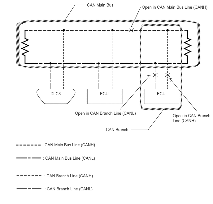 Tip:
Tip:These waveforms are measured between terminals CANH and GND, and terminals CANL and GND of the DLC3. (Use this as a reference for diagnosis of CAN communication lines.)
When malfunctions in multiple ECUs are suspected based on the CAN bus check and DTCs checked using the GTS, check the resistance of the CAN bus using an ohmmeter first. If no problems are found, check the following waveforms.
If a waveform is not similar to one of the following 3 patterns (Group 1), then an open in a CAN main bus line, an open in a CAN branch line, or a short between a CAN line (CANH or CANL) and ground is suspected (Group 2).
Wiggle the connector and wire harness to check if the waveform changes.
CAN bus waveforms (Group 1)
-
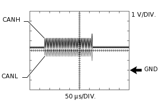
Normal waveform
-
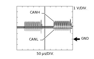
Open in both of the lines (CANH and CANL) of a CAN branch
Tip:Waveforms (waveforms shown using dotted lines) are not present from an ECU or sensor connected to a CAN branch with an open circuit in both lines. (Waveforms from other ECUs or sensors are normal.)
Because this waveform is similar to a normal waveform, instead of using the waveform, the malfunctioning part can be narrowed down by performing a CAN bus check.
-
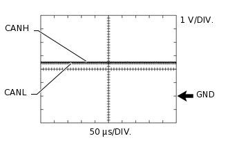
Short between the CAN bus lines (CANH and CANL)
Tip:Waveforms disappear.
If the malfunction is in an ECU, disconnecting the ECU will change the waveform. If the waveform does not change, a malfunction in the wire harness is suspected.
-
CAN bus waveforms (reference) (Group 2)
Note:The following CAN bus waveforms can be used only as reference. The actual measured waveform may differ significantly depending on the location of the open or short circuit.
-
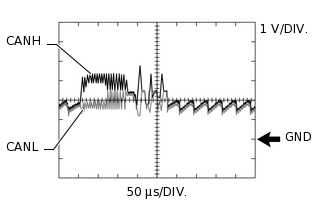
Open in a CAN branch line (CANH)
Tip:An abnormal waveform is output from an ECU with an open in one of its CAN branch lines. Because this abnormal output interferes with the signals from other ECUs, the output of other ECUs will also appear abnormal.
Narrow down the malfunctioning part by checking DTCs or performing a CAN bus check, or by checking waveform changes when ECUs or sensors are disconnected. The waveform will change to one for an open in both sides of a CAN branch when the ECU or sensor with an open CAN branch line is disconnected.
-
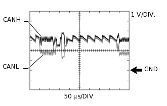
Open in a CAN branch line (CANL)
Tip:An abnormal waveform is output from an ECU with an open in one of its CAN branch lines. Because this abnormal output interferes with the signals from other ECUs, the output of other ECUs will also appear abnormal.
Narrow down the malfunctioning part by checking DTCs or performing a CAN bus check, or by checking waveform changes when ECUs or sensors are disconnected. The waveform will change to one for an open in both sides of a CAN branch when the ECU or sensor with an open CAN branch line is disconnected.
-
Open in a CAN main bus line (CANH)
Tip:Waveforms of ECUs or sensors that are closer to the DLC3 than the open part are almost normal.
Waveforms of ECUs or sensors that are on the opposite side of the DLC3 from the open part are abnormal.
An open in a CAN main bus line can be confirmed by measuring the resistance between the CANH and CANL terminals of any CAN branch.
-
Short between a CAN bus line (CANH) and ground
Tip:Narrow down the shorted part by checking for waveform changes when disconnecting connectors from the CAN junction connectors or when disconnecting ECUs or sensors.
A short to ground in the CANH line can be confirmed by measuring the resistance between CANH and ground using an ohmmeter.
-
Short between a CAN bus line (CANL) and ground
Tip:Narrow down the shorted part by checking for waveform changes when disconnecting connectors from the CAN junction connectors or when disconnecting ECUs or sensors.
A short to ground in the CANL line can be confirmed by measuring the resistance between CANL and ground using an ohmmeter.
-
DATA SENDING/RECEIVING TABLE
Data sending/receiving table
Tip:If Data List items related to sent/received data are not displayed properly, the part for which communication is interrupted can be determined using the table below.
Data Content
Data Detected and Sent by
Data Received by
(Can be Checked in the Data List)
Data Received by
(Cannot be Checked in the Data List)
Relevant Data List Item
[Selected System]
Engine speed
ECM
Brake actuator assembly
Power steering ECU assembly
Combination meter assembly
Certification ECU (smart key ECU assembly)
Engine stop and start ECU
Airbag sensor assembly
Air conditioning amplifier assembly
Main body ECU (multiplex network body ECU)
Radio and display receiver assembly
Clearance warning ECU assembly
Engine Speed [Engine and ECT] (except 8NR-FTS)
Engine Speed [Engine] (for 8NR-FTS)
Engine Revolutions [ABS/VSC/TRC]
Engine Revolution [EMPS]
Engine Rpm [Combination Meter]
Engine Speed [Starting Control]
Engine Spd (ECM) [Stop and Start]
Accelerator position
ECM (1NR-FE/1ZR-FAE/1ZR-FE/2ZR-FE/8NR-FTS)
Brake actuator assembly
Engine stop and start ECU
Pre-crash safety city sensor
Accelerator Position [Engine and ECT] (except 8NR-FTS)
Accelerator Position [Engine] (for 8NR-FTS)
Accelerator Opening Angle % [ABS/VSC/TRC]
Accelerator Position [Stop and Start]
Accel position
ECM (1ND-TV/1WW)
Brake actuator assembly
Engine stop and start ECU
Pre-crash safety city sensor
Accel Position [Engine and ECT]
Accelerator Opening Angle % [ABS/VSC/TRC]
Accelerator Position [Stop and Start]
Shift position
ECM (1NR-FE/1WW)
Certification ECU (smart key ECU assembly)
Radio and display receiver assembly
Engine stop and start ECU
Airbag sensor assembly
Main body ECU (multiplex network body ECU)
Combination meter assembly
Clearance warning ECU assembly
Pre-crash safety city sensor
Shift P Signal [Power Source Control]
Reverse Signal [Navigation System]
Neutral Switch [Stop and Start]
Shift position
ECM (1ND-TV/1ZR-FAE/1ZR-FE/2ZR-FE/8NR-FTS)
Certification ECU (smart key ECU assembly)
Radio and display receiver assembly
Engine stop and start ECU
Airbag sensor assembly
Main body ECU (multiplex network body ECU)
Combination meter assembly
Clearance warning ECU assembly
Pre-crash safety city sensor
Neutral Position SW Signal [Engine and ECT] (except 8NR-FTS)
Neutral Position SW [Engine] (for 8NR-FTS)
Shift P Signal [Power Source Control]
Reverse Signal [Navigation System]
Neutral Switch [Stop and Start]
Engine coolant temperature
ECM
Air conditioning amplifier assembly
Combination meter assembly
Engine stop and start ECU
-
Coolant Temp [Engine and ECT] (except 8NR-FTS)
Coolant Temperature [Engine] (for 8NR-FTS)
Engine Coolant Temp [Air Conditioner]
Coolant Temperature [Combination Meter]
Coolant Temp [Stop and Start]
Vehicle speed
Brake actuator assembly
ECM
Combination meter assembly*3
Power steering ECU assembly
Engine stop and start ECU
Radio and display receiver assembly
Airbag sensor assembly
Clearance warning ECU assembly
Pre-crash safety city sensor
Vehicle Speed [ABS/VSC/TRC]
Vehicle Speed [Engine and ECT] (except 8NR-FTS)
Vehicle Speed [Engine] (for 8NR-FTS)
Vehicle Speed Meter [Combination Meter]
Meter Vehicle Velocity [EMPS]
Vehicle Spd1 (ABS/VSC) [Stop and Start]
Vehicle Speed [Navigation System]
Combination meter assembly*3
Certification ECU (smart key ECU assembly)
Air conditioning amplifier assembly
Main body ECU (multiplex network body ECU)
Vehicle Speed Meter [Combination Meter]
Vehicle Speed Signal [Power Source Control]
Wheel speed
Brake actuator assembly
Headlight swivel ECU assembly
Power steering ECU assembly
Headlight leveling ECU assembly
ECM
Engine stop and start ECU
Clearance warning ECU assembly
Pre-crash safety city sensor
FR Wheel Speed [ABS/VSC/TRC]
FL Wheel Speed [ABS/VSC/TRC]
RR Wheel Speed [ABS/VSC/TRC]
RL Wheel Speed [ABS/VSC/TRC]
FR Wheel Speed [AFS]
FL Wheel Speed [AFS]
Wheel Speed Right [EMPS]
Wheel Speed Left [EMPS]
Front Right Wheel Speed Value [HL AutoLeveling]
Front Left Wheel Speed Value [HL AutoLeveling]
Ambient temperature
Air conditioning amplifier assembly
ECM (1NR-FE/1ZR-FAE/1ZR-FE/1WW/2ZR-FE/8NR-FTS)
Engine stop and start ECU
Main body ECU (multiplex network body ECU)
Clearance warning ECU assembly
Pre-crash safety city sensor
Ambient Temp Sensor [Air Conditioner]
Ambient Temp for A/C [Engine and ECT] (for 1ZR-FAE, 1ZR-FE or 2ZR-FE)
Ambient Temperature [Engine and ECT] (for 1NR-FE or 1WW)
Ambient Temp for A/C [Engine] (for 8NR-FTS)
Ambient Temp Sensor [Stop and Start]
Driver door courtesy switch
Main body ECU (multiplex network body ECU)
Engine stop and start ECU
ECM
Certification ECU (smart key ECU assembly)
Combination meter assembly*2
FL Door Courtesy SW [Main Body]*4
FR Door Courtesy SW [Main Body]*5
D Courtesy Switch Signal [Stop and Start]
Ignition switch condition
Main body ECU (multiplex network body ECU)
-
Certification ECU (smart key ECU assembly)*1
IG SW [Main Body]
Steering angle sensor
Steering sensor (spiral cable with sensor sub-assembly)
Brake actuator assembly
Power steering ECU assembly
Airbag sensor assembly
Clearance warning ECU assembly
Engine stop and start ECU
Pre-crash safety city sensor
Steering Angle Sensor [ABS/VSC/TRC]
Steering Angle [EMPS]
Yaw rate sensor
Airbag sensor assembly
Brake actuator assembly
Clearance warning ECU assembly
Headlight swivel ECU assembly
Power steering ECU assembly
Pre-crash safety city sensor
Yaw Rate Sensor [ABS/VSC/TRC]
Deceleration sensor
Airbag sensor assembly
Brake actuator assembly
Engine stop and start ECU
ECM
Clearance warning ECU assembly
Power steering ECU assembly
Pre-crash safety city sensor
Deceleration Sensor [ABS/VSC/TRC]
Deceleration Sensor2 [ABS/VSC/TRC]
Dec Sensor Calibration [Stop and Start]
Power steering assist current value
Power steering ECU assembly
Engine stop and start ECU
Clearance warning ECU assembly
Motor Actual Current [EMPS]
EPS Load [Stop and Start]
Eco drive control mode
Engine stop and start ECU
Power steering ECU assembly
ECM
Brake actuator assembly
Air conditioning amplifier assembly
Radio and display receiver assembly
Certification ECU (smart key ECU assembly)
Clearance warning ECU assembly
Stop&Start of Eng State [Stop and Start]
Stop&Start Ctrl Mode [EMPS]
Side turn signal
Combination meter assembly
-
Clearance warning ECU assembly
Pre-crash safety city sensor
-
Brake actuator assembly power source voltage*1
Brake actuator assembly
-
-
IG1 Voltage Value [ABS/VSC/TRC]
Power steering ECU assembly power source voltage*1
Power steering ECU assembly
-
-
IG Power Supply [EMPS]
Driver door touch sensor*1
Certification ECU (smart key ECU assembly)
-
-
D-Door Touch Sensor [Entry&Start]
ECM power source voltage*1
ECM
-
-
Battery Voltage [Engine and ECT] (except 8NR-FTS)
Battery Voltage [Engine] (for 8NR-FTS)
Combination meter assembly power source voltage*1
Combination meter assembly
-
-
+B Voltage Value [Combination Meter]
Solar sensor*1
Air conditioning amplifier assembly
-
-
Solar Sensor (D Side) [Air Conditioner]
Headlight swivel ECU assembly power source voltage*1
Headlight swivel ECU assembly
-
-
+B [AFS]
Headlight leveling ECU assembly power source voltage*1
Headlight leveling ECU assembly
-
-
+B [HL AutoLeveling]
Engine stop and start ECU power source voltage*1
Engine stop and start ECU
-
-
Battery Voltage [Stop and Start]
Radio and display receiver assembly power source voltage*1
Radio and display receiver assembly
-
-
Battery Voltage [Navigation System]
*1: Whether the ECU that sends data is functioning or not can be judged by using the GTS to check items such as switches or sensors that send signals to the ECU via direct lines.
*2: Although the received contents cannot be checked in the Data List, whether or not the data is received normally can be checked by observing the combination meter.
*3: The combination meter assembly receives a vehicle speed signal from the brake actuator assembly and sends the signal to other ECUs.
*4: for LHD
*5: for RHD
Details of relevant Data List items (Selected system: Engine and ECT) (for 1ZR-FAE)
Tip:Using the GTS to read the Data List allows the values or states of switches, sensors, actuators and other items to be read without removing any parts. This non-intrusive inspection can be very useful because intermittent conditions or signals may be discovered before parts or wiring is disturbed. Reading the Data List information early in troubleshooting is one way to save diagnostic time.
Note:In the table below, the values listed under "Normal Condition" are reference values. Do not depend solely on these reference values when deciding whether a part is faulty or not.
The actual values may differ from the values listed in the chart under "Results of real-vehicle check" due to climate, weather conditions, etc.
Tip:Normal Condition: If no conditions are specifically stated for "idling", the shift lever should be in N (neutral) or P, the A/C switch should be off and all accessory switches should be off.
Warm up the engine.
Turn the A/C switch off.
Turn the ignition switch off.
Connect the GTS to the DLC3.
Turn the ignition switch to ON.
Turn the GTS on.
Enter the following menus: Powertrain / Engine and ECT / Data List.
Read the Data List according to the display on the GTS.
Powertrain > Engine and ECT > Data List
Tester Display
Measurement Item
Range
Normal Condition
Reference Value
Diagnostic Note
Vehicle Speed
Vehicle speed
Min.: 0 km/h (0 mph), Max.: 255 km/h (158 mph)
Actual vehicle speed
-
This is the current vehicle speed.
The vehicle speed is detected using the wheel speed sensors.
-
Vehicle speed data is delayed when it is displayed. Therefore, even if the vehicle speed listed in the freeze frame data is 0 km/h (0 mph), this does not always mean that the malfunction occurred when the vehicle was stopped.
To accurately confirm whether the vehicle was stopped or not, use "SPD (NO)", which is the CVT output speed (for CVT models).
Engine Speed
Engine speed
Min.: 0 rpm, Max.: 16383 rpm
600 to 700 rpm: Idling (for CVT models)
580 to 680 rpm: Idling (for manual transaxle models)
Idling (engine warmed up and A/C off): 747 rpm
When the crankshaft position sensor is malfunctioning, "Engine Speed" is approximately 0 rpm or varies greatly from the actual engine speed.
Coolant Temp
Coolant temperature
Min.: -40°C (-40°F), Max.: 140°C (284°F)
75 to 100°C (167 to 212°F): After warming up
-
This is the engine coolant temperature.
Tip:After warming up the engine, the engine coolant temperature is 75 to 100°C (167 to 212°F).
After a long soak, the engine coolant temperature, intake air temperature and ambient air temperature are approximately equal.
If the value is -40°C (-40°F), or 140°C (284°F), the sensor circuit is open or shorted.
Check if the engine overheats when the value indicates 140°C (284°F).
Battery Voltage
Battery voltage
Min.: 0 V, Max.: 65.535 V
11 to 14 V: Idling
Ignition switch ON: 12.734 V
Cranking: 10.839 V
Idling (engine warmed up): 14.101 V
If 11 V or less, characteristics of some electrical components may change.
Accelerator Position
Accelerator pedal position
Min.: 0%, Max.: 399.9%
Actual accelerator pedal position
Ignition switch ON: 0.0% (accelerator pedal fully released)
Ignition switch ON: 100.0% (accelerator pedal fully depressed)
This is the accelerator pedal position defined using the learned fully released position (sensor output) of accelerator pedal position sensor No. 1 as 0% and the fully depressed position as 100%.
Neutral Position SW Signal
Park/Neutral position switch status
ON or OFF
ON: Shift lever in P or N
-
This item is displayed only CVT models.
Ambient Temp for A/C
Ambient temperature for A/C
Min.: -40°C (-40°F), Max.: 215°C (419°F)
-
-
-
Details of relevant Data List items (Selected system: Engine and ECT) (for 1ZR-FE)
Tip:Using the GTS to read the Data List allows the values or states of switches, sensors, actuators and other items to be read without removing any parts. This non-intrusive inspection can be very useful because intermittent conditions or signals may be discovered before parts or wiring is disturbed. Reading the Data List information early in troubleshooting is one way to save diagnostic time.
Note:In the table below, the values listed under "Normal Condition" are reference values. Do not depend solely on these reference values when deciding whether a part is faulty or not.
The actual values may differ from the values listed in the chart under "Reference Value" due to climate, weather conditions, etc.
Tip:Normal Condition: If no conditions are specifically stated for "idling", the shift lever should be in N (neutral) or P, the A/C switch should be off and all accessory switches should be off.
Warm up the engine.
Turn the A/C switch off.
Turn the ignition switch off.
Connect the GTS to the DLC3.
Turn the ignition switch to ON.
Turn the GTS on.
Enter the following menus: Powertrain / Engine and ECT / Data List.
According to the display on the GTS, read the Data List.
Powertrain > Engine and ECT > Data List
Tester Display
Measurement Item
Range
Normal Condition
Diagnostic Note
Vehicle Speed
Vehicle speed
Min.: 0 km/h (0 mph), Max.: 255 km/h (158 mph)
Actual vehicle speed
This is the current vehicle speed.
The vehicle speed is detected using the wheel speed sensors.
-
Vehicle speed data is delayed when it is displayed. Therefore, even if the vehicle speed listed in the freeze frame data is 0 km/h (0 mph), this does not always mean that the malfunction occurred when the vehicle was stopped.
To accurately confirm whether the vehicle was stopped or not, use "SPD (NOUT)", which is the CVT output speed (for CVT models).
Engine Speed
Engine speed
Min.: 0 rpm, Max.: 16383 rpm
600 to 700 rpm: Idling
When the crankshaft position sensor is malfunctioning, "Engine Speed" is approximately 0 rpm or varies greatly from the actual engine speed.
Coolant Temp
Coolant temperature
Min.: -40°C (-40°F), Max.: 140°C (284°F)
75 to 100°C (167 to 212°F): After warming up
This is the engine coolant temperature.
Tip:After warming up the engine, the engine coolant temperature is 75 to 100°C (167 to 212°F).
After a long soak, the engine coolant temperature, intake air temperature and ambient air temperature are approximately equal.
If the value is -40°C (-40°F), or higher than 135°C (275°F), the sensor circuit is open or shorted.
Check if the engine overheats when the value indicates higher than 135°C (275°F).
Battery Voltage
Battery voltage
Min.: 0 V, Max.: 65.535 V
11 to 14 V: Idling
If 11 V or less, characteristics of some electrical components may change.
Accelerator Position
Accelerator pedal position
Min.: 0%, Max.: 399.9%
Actual accelerator pedal position
This is the accelerator pedal position defined using the learned fully released position (sensor output) of accelerator pedal position sensor No. 1 as 0% and the fully depressed position as 100%.
Neutral Position SW Signal
Park/Neutral position switch status
ON or OFF
ON: Shift lever in P or N
This item is display only CVT models.
Ambient Temp for A/C
Ambient temperature for A/C
Min.: -40°C (-40°F), Max.: 215°C (419°F)
-
-
Details of relevant Data List items (Selected system: Engine and ECT) (for 2ZR-FE)
Tip:Using the GTS to read the Data List allows the values or states of switches, sensors, actuators and other items to be read without removing any parts. This non-intrusive inspection can be very useful because intermittent conditions or signals may be discovered before parts or wiring is disturbed. Reading the Data List information early in troubleshooting is one way to save diagnostic time.
Note:In the table below, the values listed under "Normal Condition" are reference values. Do not depend solely on these reference values when deciding whether a part is faulty or not.
The actual values may differ from the values listed in the chart under "Reference Value" due to climate, weather conditions, etc.
Tip:Normal Condition: If no conditions are specifically stated for "idling", the shift lever should be in N or P, the A/C switch should be off and all accessory switches should be off.
Warm up the engine.
Turn the A/C switch off.
Turn the ignition switch off.
Connect the GTS to the DLC3.
Turn the ignition switch to ON.
Turn the GTS on.
Enter the following menus: Powertrain / Engine and ECT / Data List.
According to the display on the GTS, read the Data List.
Powertrain > Engine and ECT > Data List
Tester Display
Measurement Item
Range
Normal Condition
Diagnostic Note
Vehicle Speed
Vehicle speed
Min.: 0 km/h (0 mph), Max.: 255 km/h (158 mph)
Actual vehicle speed
Stored as Freeze Frame Data: Yes
This is the current vehicle speed.
The vehicle speed is detected using the wheel speed sensors.
-
Vehicle speed data is delayed when it is displayed. Therefore, even if the vehicle speed listed in the freeze frame data is 0 km/h (0 mph), this does not always mean that the malfunction occurred when the vehicle was stopped.
To accurately confirm whether the vehicle was stopped or not, use "SPD (NOUT)", which is the CVT output speed.
Engine Speed
Engine speed
Min.: 0 rpm, Max.: 16383 rpm
600 to 700 rpm: Idling
Stored as Freeze Frame Data: Yes
When the crankshaft position sensor is malfunctioning, "Engine Speed" is approximately 0 rpm or varies greatly from the actual engine speed.
Coolant Temp
Coolant temperature
Min.: -40°C (-40°F), Max.: 140°C (284°F)
75 to 100°C (167 to 212°F): After warming up
Stored as Freeze Frame Data: Yes
This is the engine coolant temperature.
Tip:After warming up the engine, the engine coolant temperature is 75 to 100°C (167 to 212°F).
After a long soak, the engine coolant temperature, intake air temperature and ambient air temperature are approximately equal.
If the value is -40°C (-40°F), or 140°C (284°F), the sensor circuit is open or shorted.
Check if the engine overheats when the value indicates 140°C (284°F).
Battery Voltage
Battery voltage
Min.: 0 V, Max.: 65.535 V
11 to 14 V: Idling
Stored as Freeze Frame Data: Yes
If 11 V or less, characteristics of some electrical components may change.
Accelerator Position
Accelerator pedal position
Min.: 0%, Max.: 399.9%
Actual accelerator pedal position
Stored as Freeze Frame Data: No
This is the accelerator pedal position defined using the learned fully released position (sensor output) of accelerator pedal position sensor No. 1 as 0% and the fully depressed position as 100%.
Neutral Position SW Signal
Park/Neutral position switch status
ON or OFF
ON: Shift lever in P or N
Stored as Freeze Frame Data: Yes
Ambient Temp for A/C
Ambient temperature for A/C
Min.: -40°C (-40°F), Max.: 215°C (419°F)
-
Stored as Freeze Frame Data: Yes
Details of relevant Data List items (Selected system: Engine and ECT) (for 1NR-FE)
Tip:Using the GTS to read the Data List allows the values or states of switches, sensors, actuators and other items to be read without removing any parts. This non-intrusive inspection can be very useful because intermittent conditions or signals may be discovered before parts or wiring is disturbed. Reading the Data List information early in troubleshooting is one way to save diagnostic time.
Note:In the table below, the values listed under "Normal Condition" are reference values. Do not depend solely on these reference values when deciding whether a part is faulty or not.
Tip:Normal Condition: If no conditions are specifically stated for "idling", the shift lever should be in N (neutral) or P, the A/C switch should be off and all accessory switches should be off.
Warm up the engine.
Turn the A/C switch off.
Turn the ignition switch off.
Connect the GTS to the DLC3.
Turn the ignition switch to ON.
Turn the GTS on.
Enter the following menus: Powertrain / Engine and ECT / Data List.
According to the display on the GTS, read the Data List.
Powertrain > Engine and ECT > Data List
Tester Display
Measurement Item
Range
Normal Condition
Diagnostic Note
Vehicle Speed
Vehicle speed
Min.: 0 km/h (0 mph), Max.: 255 km/h (158 mph)
Actual vehicle speed
Stored as Freeze Frame Data: Yes
This is the current vehicle speed.
The vehicle speed is detected using the wheel speed sensors.
-
Vehicle speed data is delayed when it is displayed. Therefore, even if the vehicle speed listed in the freeze frame data is 0 km/h (0 mph), this does not always mean that the malfunction occurred when the vehicle was stopped.
Engine Speed
Engine speed
Min.: 0 rpm, Max.: 16383 rpm
600 to 700 rpm: Idling with warm engine, shift lever in neutral, A/C off
Stored as Freeze Frame Data: Yes
When the crankshaft position sensor is malfunctioning, "Engine Speed" is approximately 0 rpm or varies greatly from the actual engine speed.
Coolant Temp
Coolant temperature
Min.: -40°C (-40°F), Max.: 140°C (284°F)
75 to 100°C (167 to 212°F): After warming up
Stored as Freeze Frame Data: Yes
This is the engine coolant temperature.
Tip:After warming up the engine, the engine coolant temperature is 75 to 100°C (167 to 212°F).
After a long soak, the engine coolant temperature, intake air temperature and ambient temperature are approximately equal.
If the value is -40°C (-40°F), or 140°C (284°F), the sensor circuit is open or shorted.
Check if the engine overheats when the value indicates 140°C (284°F).
Ambient Temperature
Ambient temperature
Min.: -40°C (-40°F), Max.: 215°C (419°F)
Equivalent to ambient air temperature
Stored as Freeze Frame Data: Yes
Battery Voltage
Battery voltage
Min.: 0 V, Max.: 65.535 V
11 to 14 V: Idling
Stored as Freeze Frame Data: Yes
If 11 V or less, characteristics of some electrical components may change.
Accelerator Position
Accelerator pedal position
Min.: 0%, Max.: 399.9%
Actual accelerator pedal position
Stored as Freeze Frame Data: No
This is the accelerator pedal position defined using the learned fully released position (sensor output) of accelerator pedal position sensor No. 1 as 0% and the fully depressed position as 100%.
Details of relevant Data List items (Selected system: Engine and ECT) (for 1ND-TV)
Tip:Using the GTS to read the Data List allows the values or states of switches, sensors, actuators and other items to be read without removing any parts. This non-intrusive inspection can be very useful because intermittent conditions or signals may be discovered before parts or wiring is disturbed. Reading the Data List information early in troubleshooting is one way to save diagnostic time.
Note:In the table below, the values listed under "Normal Condition" are reference values. Do not depend solely on these reference values when deciding whether a part is faulty or not.
Tip:When reading values of the Data List, confirm that PM regeneration is not activated (value of "After Injection Period" is 0) by entering the following menus: Powertrain / Engine and ECT / Data List / After Injection Period.
If PM regeneration is activated (value of "After Injection Period" is not 0), drive the vehicle until PM regeneration is complete (value of "After Injection Period" becomes 0).
When idling, EGR cut occurs under either of the following conditions:
-
PM regeneration is activated.
Idling time is long (approximately 20 minutes or more).
If EGR is cut off when idling and PM regeneration is not activated, when the vehicle is driven in 4th gear between 90 and 100 km/h (56 and 62 mph) for 30 minutes, EGR resumes.
Warm up the engine.
Turn the ignition switch off.
Connect the GTS to the DLC3.
Turn the ignition switch to ON.
Start the engine.
Turn the GTS on.
Enter the following menus: Powertrain / Engine and ECT / Data List.
Read the Data List according to the display on the GTS.
Powertrain > Engine and ECT > Data List
Tester Display
Measurement Item
Range
Normal Condition
Reference Value
Diagnostic Note
Vehicle Speed
Vehicle speed
Min.: 0 km/h, Max.: 255 km/h
Actual vehicle speed
-
Cause of Out of Range:
Speed sensor
Speed sensor circuit
Engine Speed
Engine speed
Min.: 0 rpm, Max.: 16383 rpm
Idling: 720 to 820 rpm
Idling ("Coolant Temp" = 77°C [171°F]): 770 rpm
When the crankshaft position sensor is malfunctioning, "Engine speed" is approximately 0 or varies greatly from the actual engine speed.
Cause of Out of Range:
Crankshaft position sensor
Crankshaft position sensor circuit
Coolant Temp
Engine coolant temperature
Min.: -40°C, Max.: 140°C
After warming up engine: 75 to 100°C (167 to 212°F)
After warming up engine: 75°C (167°F)
After a long soak, the coolant temperature, intake air temperature, and ambient air temperature are approximately equal.
If the value is 30°C (-22°F) or less or 120°C (248°F) or more, the sensor circuit is open or shorted.
Cause of Out of Range:
Engine coolant temperature sensor
Thermostat
Symptoms when out of range:
Difficult starting when engine is cold, rough idle, black smoke, lack of power
Battery Voltage
Battery voltage
Min.: 0 V, Max.: 65.535 V
Ignition switch ON: 11 to 14 V
Ignition switch ON: 12.080 V
Idling: 13.980 V
If 11 V or less, characteristics of some electrical components change.
Symptoms when out of range:
If 5 V or less, starting becomes difficult
Accel Position
Accelerator position status
Min.: 0%, Max.: 100%
Accelerator pedal released:
0%
Accelerator pedal fully depressed:
100%
Ignition switch ON: 0.00% (accelerator pedal released)
Running without load (2500 rpm): 35.29%
Running without load (4000 rpm): 65.88%
"Accel Position" is the accelerator opening angle (%) for engine control use.
Details of relevant Data List items (Selected system: Engine) (for 8NR-FTS)
Tip:Using the GTS to read the Data List allows the values or states of switches, sensors, actuators and other items to be read without removing any parts. This non-intrusive inspection can be very useful because intermittent conditions or signals may be discovered before parts or wiring is disturbed. Reading the Data List information early in troubleshooting is one way to save diagnostic time.
Note:In the table below, the values listed under "Normal Condition" are reference values. Do not depend solely on these reference values when deciding whether a part is faulty or not.
The actual values may differ from the values listed in the chart under "Reference Value" due to climate, weather conditions, etc.
The values listed under "Reference Value" are those of an inspection performed in NORMAL mode. The actual values may differ if inspected in SPORT mode.
Tip:Normal Condition: If no conditions are specifically stated for "idling", the shift lever should be in N (Neutral) or P, the A/C switch and all accessories should be off.
Warm up the engine.
Turn the A/C switch off.
Turn the ignition switch off.
Connect the GTS to the DLC3.
Turn the ignition switch to ON.
Turn the GTS on.
Enter the following menus: Powertrain / Engine / Data List.
According to the display on the GTS, read the Data List.
Powertrain > Engine > Data List
Tester Display
Measurement Item
Range
Normal Condition
Reference Value
Diagnostic Note
Vehicle Speed
Vehicle speed
Min.: 0 km/h (0 mph), Max.: 255 km/h (158 mph)
Actual vehicle speed
-
This is the current vehicle speed.
The vehicle speed is detected using the wheel speed sensors.
-
There is a delay in when the vehicle speed data is displayed. Therefore, even if the vehicle speed listed in the freeze frame data is 0 km/h (0 mph), this does not always mean that the malfunction occurred when the vehicle was stopped.
Engine Speed
Engine speed
Min.: 0 rpm, Max.: 16383 rpm
680 to 780 rpm: Idling (shift lever in N, engine warmed up and A/C off) (CVT models)
600 to 700 rpm: Idling (shift lever in neutral, engine warmed up and A/C off) (M/T models)
Idling (engine warmed up and A/C off): 710 rpm (CVT models)
When the crankshaft position sensor is malfunctioning, "Engine Speed" is approximately 0 rpm or varies greatly from the actual engine speed.
Coolant Temperature
Engine coolant temperature
Min.: -40°C (-40°F), Max.: 140°C (284°F)
75 to 100°C (167 to 212°F): After warming up
-
This is the engine coolant temperature.
Tip:After warming up the engine, the engine coolant temperature will be 75 to 100°C (167 to 212°F).
After a long soak, the engine coolant temperature, intake air temperature and ambient air temperature will be approximately equal.
If the value is -40°C (-40°F), or 140°C (284°F), the sensor circuit is open or shorted.
Check if the engine overheats if the value indicated is higher than 140°C (284°F).
Battery Voltage
Battery voltage
Min.: 0 V, Max.: 65.5 V
11 to 14 V: Idling
Ignition switch ON: 12.617 V
Cranking: 10.488 V
Idling (engine warmed up): 14.062 V
If 11 V or less, characteristics of some electrical components may change.
Accelerator Position
Accelerator pedal position
Min.: 0%, Max.: 399.9%
Actual accelerator pedal position
Ignition switch ON, accelerator pedal fully released: 0.0%
Ignition switch ON, accelerator pedal fully depressed: 100.0%
This is the accelerator pedal position defined using the learned fully released position (sensor output) of No. 1 accelerator pedal position sensor as 0% and the fully depressed position as 100%.
Neutral Position SW
Park/Neutral position switch status
ON or OFF
ON: Shift lever in P or N (CVT models)
ON: Clutch pedal depressed (M/T models)
-
-
Ambient Temp for A/C
Ambient temperature for A/C
Min.: -40°C (-40°F), Max.: 215°C (419°F)
-
-
-
Details of relevant Data List items (Selected system: Engine and ECT) (for 1WW)
Note:In the table below, the values listed under "Normal Condition" are reference values. Do not depend solely on these reference values when deciding whether a part is faulty or not.
The actual values may differ from the values listed in the chart under "Reference Value" due to climate, weather conditions, etc.
Tip:Using the GTS to read the Data List allows the values or states of switches, sensors, actuators and other items to be read without removing any parts. This non-intrusive inspection can be very useful because intermittent conditions or signals may be discovered before parts or wiring is disturbed. Reading the Data List information early in troubleshooting is one way to save diagnostic time.
Warm up the engine.
Turn the ignition switch off.
Connect the GTS to the DLC3.
Turn the ignition switch to ON.
Start the engine.
Turn the GTS on.
Enter the following menus: Powertrain / Engine and ECT / Data List.
Powertrain > Engine and ECT > Data List
Tester Display
Measurement Item
Range
Normal Condition
Reference Value
Diagnostic Note
Vehicle Speed
Vehicle speed
Min.: 0 km/h, Max.: 255 km/h
Actual vehicle speed
-
-
Engine Speed
Engine speed
Min.: 0 rpm, Max.: 16383 rpm
-
Idling (warm up the engine): 830 rpm
-
Coolant Temp
Engine coolant temperature
Min.: -40°C, Max.: 215°C
After warming up engine: 75 to 90°C (167 to 194°F)
-
-
Ambient Temperature
Ambient temperature value
Min.: -40°C, Max.: 215°C
Actual ambient temperature
-
-
Battery Voltage
Battery voltage
Min.: 0 V, Max.: 65.535 V
Ignition switch ON: 11 to 14 V
-
-
Details of relevant Data List items (Selected system: Power Source Control)
Note:In the table below, the values listed under "Normal Condition" are reference values. Do not depend solely on these reference values when deciding whether a part is faulty or not.
Tip:Using the GTS to read the Data List allows the values or states of switches, sensors, actuators and other items to be read without removing any parts. This non-intrusive inspection can be very useful because intermittent conditions or signals may be discovered before parts or wiring is disturbed. Reading the Data List information early in troubleshooting is one way to save diagnostic time.
Connect the GTS to the DLC3.
Turn the ignition switch to ON.
Turn the GTS on.
Enter the following menus: Body Electrical / Power Source Control / Data List.
Read the Data List according to the display on the GTS.
Body Electrical > Power Source Control > Data List
Tester Display
Measurement Item
Range
Normal Condition
Diagnostic Note
Shift P Signal
Shift position P*
ON or OFF
ON: Shift lever in P
OFF: Shift lever not in P
Use this item to determine if the shift position switch is malfunctioning.
The engine cannot be started when this item is OFF.
Vehicle Speed Signal
Vehicle being driven or stopped
Stop or Run
Stop: Vehicle stopped
Run: Vehicle being driven at 5 km/h (3 mph) or more
-
*: for CVT
Details of relevant Data List items (Selected system: ABS/VSC/TRC)
Note:In the table below, the values listed under "Normal Condition" are reference values. Do not depend solely on these reference values when deciding whether a part is faulty or not.
Tip:Using the GTS to read the Data List allows the values or states of switches, sensors, actuators and other items to be read without removing any parts. This non-intrusive inspection can be very useful because intermittent conditions or signals may be discovered before parts or wiring is disturbed. Reading the Data List information early in troubleshooting is one way to save diagnostic time.
Warm up the engine.
Turn the ignition switch off.
Connect the GTS to the DLC3.
Turn the ignition switch to ON.
Turn the GTS on.
Enter the following menus: Chassis / ABS/VSC/TRC / Data List.
Read the Data List according to the display on the GTS.
Chassis > ABS/VSC/TRC > Data List
Tester Display
Measurement Item
Range
Normal Condition
Diagnostic Note
Deceleration Sensor
Acceleration sensor reading*
Min.: -18.525 m/s2, Max.: 18.387 m/s2
-
During deceleration/acceleration: Changes continuously
Deceleration Sensor2
Acceleration sensor 2 reading*
Min.: -18.525 m/s2, Max.: 18.387 m/s2
-
During deceleration/acceleration: Changes continuously
Yaw Rate Sensor
Yaw rate sensor*
Min.: -128°/s, Max.: 127°/s
Vehicle stopped: 0 °/s
Turning right: -128 to 0 °/s
Turning left: 0 to 127 °/s
-
Steering Angle Sensor
Steering angle sensor*
Min.: -3276.8°, Max.: 3276.7°
Turning left: Increases
Turning right: Decreases
-
FR Wheel Speed
Front wheel speed sensor RH reading
Min.: 0 km/h (0 mph), Max.: 326 km/h (202 mph)
Vehicle stopped: 0 km/h (0 mph)
When driving at constant speed: No large fluctuations
FL Wheel Speed
Front wheel speed sensor LH reading
Min.: 0 km/h (0 mph), Max.: 326 km/h (202 mph)
Vehicle stopped: 0 km/h (0 mph)
When driving at constant speed: No large fluctuations
RR Wheel Speed
Rear wheel speed sensor RH reading
Min.: 0 km/h (0 mph), Max.: 326 km/h (202 mph)
Vehicle stopped: 0 km/h (0 mph)
When driving at constant speed: No large fluctuations
RL Wheel Speed
Rear wheel speed sensor LH reading
Min.: 0 km/h (0 mph), Max.: 326 km/h (202 mph)
Vehicle stopped: 0 km/h (0 mph)
When driving at constant speed: No large fluctuations
Vehicle Speed
Maximum wheel speed sensor reading
Min.: 0 km/h (0 mph), Max.: 326 km/h (202 mph)
Vehicle stopped: 0 km/h (0 mph)
When driving at constant speed: No large fluctuations
Engine Revolutions
Engine speed*
Min.: 0 rpm, Max.: 65535 rpm
Engine stopped: 0 rpm
When engine speed is constant: No large fluctuations
Accelerator Opening Angle %
Percentage of accelerator pedal opening angle*
Min.: 0.0%, Max.: 128.0%
Accelerator pedal released: 0%
During accelerator pedal operation: Changes in proportion with the pedal movement
IG1 Voltage Value
IG1 voltage value
Min.: 0.00 V, Max.: 20.00 V
-
Changes in proportion to battery voltage
*: w/ VSC
Details of relevant Data List items (Selected system: EMPS)
Note:In the table below, the values listed under "Normal Condition" are reference values. Do not depend solely on these reference values when deciding whether a part is faulty or not.
Tip:Using the GTS to read the Data List allows the values or states of switches, sensors, actuators and other items to be read without removing any parts. This non-intrusive inspection can be very useful because intermittent conditions or signals may be discovered before parts or wiring is disturbed. Reading the Data List information early in troubleshooting is one way to save diagnostic time.
Turn the ignition switch off.
Connect the GTS to the DLC3.
Turn the ignition switch to ON.
Turn the GTS on.
Enter the following menus: Chassis / EMPS / Data List.
Read the Data List according to the display on the GTS.
Chassis > EMPS > Data List
Tester Display
Measurement Item
Range
Normal Condition
Diagnostic Note
Meter Vehicle Velocity
Vehicle speed from speedometer
Min.: 0.0 km/h (0.0 MPH)
Max.: 300.0 km/h (186.4 MPH)
0 km/h (0 MPH): Engine running and vehicle stopped
No significant fluctuation: Engine running and vehicle driven at a constant speed
-
Wheel Speed Right
Rear right wheel speed
Min.: 0 km/h (0 MPH)
Max.: 255 km/h (158 MPH)
0 km/h (0 MPH): Engine running and vehicle stopped
No significant fluctuation: Engine running and vehicle driven at a constant speed
-
Wheel Speed Left
Rear left wheel speed
Min.: 0 km/h (0 MPH)
Max.: 255 km/h (158 MPH)
0 km/h (0 MPH): Engine running and vehicle stopped
No significant fluctuation: Engine running and vehicle driven at a constant speed
-
Engine Revolution
Engine speed
Min.: 0 rpm
Max.: 12800 rpm
No significant fluctuation
Engine running at a constant speed
Motor Actual Current
Amount of current to motor
Min.: -327.68 A
Max.: 327.67 A
Value changes in proportion to steering effort
- The value increases when turning left and decreases when turning right
Engine running and steering wheel being turned
IG Power Supply
IG power source voltage
Min.: 0.0000 V
Max.: 20.1531 V
8 to 16 V
Ignition switch ON
Stop&Start Ctrl Mode
Status of the record of stop and start control mode
IG, Run, Stopreq, Stop or Restart
-
-
Steering Angle
Steering angle
Min.: -3072.0 deg
Max.: 3070.5 deg
-
-
Details of relevant Data List items (Selected system: Entry&Start)
Note:In the table below, the values listed under "Normal Condition" are reference values. Do not depend solely on these reference values when deciding whether a part is faulty or not.
Tip:Using the GTS to read the Data List allows the values or states of switches, sensors, actuators and other items to be read without removing any parts. This non-intrusive inspection can be very useful because intermittent conditions or signals may be discovered before parts or wiring is disturbed. Reading the Data List information early in troubleshooting is one way to save diagnostic time.
When using the GTS with the engine switch off to troubleshoot:
Connect the GTS to the DLC3 and turn a courtesy light switch on and off at 1.5-second intervals until communication between the GTS and vehicle begins.
Connect the GTS to the DLC3.
Turn the engine switch on (IG).
Turn the GTS on.
Enter the following menus: Body Electrical / Entry&Start / Data List.
Read the Data List according to the display on the GTS.
Body Electrical > Entry&Start > Data List
Tester Display
Measurement Item
Range
Normal Condition
Diagnostic Note
D-Door Touch Sensor
Driver door touch sensor (unlock sensor)*
ON or OFF
ON: Driver door touch sensor (unlock sensor) touched
OFF: Driver door touch sensor (unlock sensor) not touched
Displays whether the unlock sensor is on or off (even if the sensor is touched and contact is maintained, "ON" is displayed only momentarily).
Use this Data List item to help determine if there is an unlock sensor malfunction when the entry unlock function does not operate.
*: Data from an actual vehicle provided for reference.
Details of relevant Data List items (Selected system: Combination Meter)
Note:In the table below, the values listed under "Normal Condition" are reference values. Do not depend solely on these reference values when deciding whether a part is faulty or not.
Tip:Using the GTS to read the Data List allows the values or states of switches, sensors, actuators and other items to be read without removing any parts. This non-intrusive inspection can be very useful because intermittent conditions or signals may be discovered before parts or wiring is disturbed. Reading the Data List information early in troubleshooting is one way to save diagnostic time.
Warm up the engine.
Turn the ignition switch off.
Connect the GTS to the DLC3.
Turn the ignition switch to ON.
Turn the GTS on.
Enter the following menus: Body Electrical / Combination Meter / Data List.
Read the Data List according to the display on the GTS.
Body Electrical > Combination Meter > Data List
Tester Display
Measurement Item
Range
Normal Condition
Diagnostic Note
Vehicle Speed Meter
Vehicle speed
Min.: 0 km/h (0 mph), Max.: 255 km/h (158 mph)
Almost the same as actual vehicle speed
-
Engine Rpm
Engine speed
Min.: 0 rpm, Max.: 12750 rpm
Almost the same as actual engine speed
-
Coolant Temperature
Engine coolant temperature
Min.: 0°C (32°F), Max.: 127.5°C (261.5°F)
except 1WW:
75 to 100 °C (167 to 212°F): After warming up engine
for 1WW:
75 to 90°C (167 to 194°F): After warming up engine
-
+B Voltage Value
Battery voltage
Min.: 0 V, Max.: 25.5 V
11 to 14 V
-
Details of relevant Data List items (Selected system: Air Conditioner)
Note:In the table below, the values listed under "Normal Condition" are reference values. Do not depend solely on these reference values when deciding whether a part is faulty or not.
Tip:Using the GTS to read the Data List allows the values or states of switches, sensors, actuators and other items to be read without removing any parts. This non-intrusive inspection can be very useful because intermittent conditions or signals may be discovered before parts or wiring is disturbed. Reading the Data List information early in troubleshooting is one way to save diagnostic time.
Connect the GTS to the DLC3.
Turn the ignition switch to ON.
Turn the GTS on.
Enter the following menus: Body Electrical / Air Conditioner / Data List.
Read the Data List according to the display on the GTS.
Body Electrical > Air Conditioner > Data List
Tester Display
Measurement Item
Range
Normal Condition
Diagnostic Note
Ambient Temp Sensor
Thermistor assembly
Min.: -23.30°C (-9.94°F)
Max.: 65.95°C (150.71°F)
Actual ambient temperature displayed
-
Solar Sensor (D Side)
Driver side cooler (solar sensor) thermistor*2 or cooler (solar sensor) thermistor*3
Min.: 0
Max.: 255
Driver side cooler (solar sensor) thermistor*2 or cooler (solar sensor) thermistor*3 value increases as brightness increases
*1
Engine Coolant Temp
Engine coolant temperature sensor
Min.: 1.30°C (34.34°F)
Max.: 90.55°C (194.99°F)
Actual engine coolant temperature is displayed
-
*1: w/ Cooler System
*2: for Dual Type
*3: for Single Type
Details of relevant Data List items (Selected system: Main Body)
Note:In the table below, the values listed under "Normal Condition" are reference values. Do not depend solely on these reference values when deciding whether a part is faulty or not.
Tip:Using the GTS to read the Data List allows the values or states of switches, sensors, actuators and other items to be read without removing any parts. This non-intrusive inspection can be very useful because intermittent conditions or signals may be discovered before parts or wiring is disturbed. Reading the Data List information early in troubleshooting is one way to save diagnostic time.
Connect the GTS to the DLC3.
Turn the ignition switch to ON.
Turn the GTS on.
Enter the following menus: Body Electrical / Main Body / Data List.
Read the Data List according to the display on the GTS.
Body Electrical > Main Body > Data List
Tester Display
Measurement Item
Range
Normal Condition
Diagnostic Note
IG SW
Ignition switch ON signal
ON or OFF
ON: Ignition switch ON
OFF: Ignition switch off
-
FR Door Courtesy SW
Front door courtesy light switch assembly RH signal
ON or OFF
ON: Front door RH open
OFF: Front door RH closed
-
FL Door Courtesy SW
Front door courtesy light switch assembly LH signal
ON or OFF
ON: Front door LH open
OFF: Front door LH closed
-
Details of relevant Data List items (Selected system: Stop and Start)
Note:In the table below, the values listed under "Normal Condition" are reference values. Do not depend solely on these reference values when deciding whether a part is faulty or not.
Tip:Using the GTS to read the Data List allows the values or states of switches, sensors, actuators and other items to be read without removing any parts. This non-intrusive inspection can be very useful because intermittent conditions or signals may be discovered before parts or wiring is disturbed. Reading the Data List information early in troubleshooting is one way to save diagnostic time.
Warm up the engine.
Turn the ignition switch off.
Connect the GTS to the DLC3.
Start the engine.
Turn the GTS on.
Enter the following menus: Powertrain / Stop and Start / Data List.
According to the display on the GTS, read the Data List.
Powertrain > Stop and Start > Data List
Tester Display
Measurement Item
Range
Normal Condition
Diagnostic Note
Coolant Temp
Engine coolant temperature
Min.: 16°C (60.8°F), Max.: 127°C (260.6°F)
75 to 95°C (167 to 203°F): Idling after engine warmed up
This is sent from the ECM.
Engine Spd (ECM)
Engine speed signal from ECM via CAN communication
Min.: 0 rpm, Max.: 12800 rpm
720 to 820 rpm: Idling after engine warmed up (for 1ND-TV)
600 to 700 rpm: Idling after engine warmed up (for 8NR-FTS with Manual Transaxle)
680 to 780 rpm: Idling after engine warmed up (for 8NR-FTS with CVT)
830 rpm: Idling after engine warmed up (for 1WW)
This is sent from the ECM.
Battery Voltage
Battery voltage
Min.: 0 V, Max.: 20 V
8 to 14 V: Idling
-
D Courtesy Switch Signal
Driver door courtesy switch signal
ON/OFF
ON: Driver side door opened
OFF: Driver side door closed
-
Neutral Switch
Neutral start switch assembly signal
ON/OFF
ON: Shift lever in neutral
OFF: Shift lever not in neutral
-
Vehicle Spd1 (ABS/VSC)
Vehicle speed signal from skid control ECU via CAN communication
Min.: 0 km/h (0 mph), Max.: 327.67 km/h (203.6 mph)
0 km/h (0 mph): Vehicle is stopped
-
Ambient Temp Sensor
Ambient temperature
Min.: -30°C (-22°F), Max.: 50°C (122°F)
Close to ambient temperature
-
Stop&Start of Eng State
Stop and start control status
IG / Run / Stopreq / Stop / Restart
IG: Before engine started
Run: Engine running
Stopreq: Engine stop requested
Stop: Engine stopped (by stop and start control)
Restart: Engine restarted
-
EPS Load
Electric power steering current
Min.: -327.68 A, Max.: 327.67 A
Approx. 0 A: EPS assist is not activated
-
Accelerator Position
Accelerator pedal position
Min.: 0%, Max.: 127.5%
Actual accelerator pedal position
-
Dec Sensor Calibration
Deceleration sensor zero point uncalibrated
Comp/Incomp
Comp: Deceleration sensor learning completed
-
Details of relevant Data List items (Selected system: Navigation System)
Note:In the table below, the values listed under "Normal Condition" are reference values. Do not depend solely on these reference values when deciding whether a part is faulty or not.
Tip:Using the GTS to read the Data List allows the values or states of switches, sensors, actuators and other items to be read without removing any parts. This non-intrusive inspection can be very useful because intermittent conditions or signals may be discovered before parts or wiring is disturbed. Reading the Data List information early in troubleshooting is one way to save diagnostic time.
Connect the GTS to the DLC3.
Turn the ignition switch to ON.
Turn the GTS on.
Enter the following menus: Body Electrical / Navigation System / Data List.
According to the display on the GTS, read the Data List.
Body Electrical > Navigation System > Data List
Tester Display
Measurement Item
Range
Normal Condition
Diagnostic Note
Battery Voltage
Battery voltage
Min.: 0 V, Max.:24 V
11 to 14 V*1
9.5 to 14 V*2
-
Reverse Signal
Reverse signal
ON or OFF
ON: Shift lever in R
OFF: Shift lever in any position other than R
-
Vehicle Speed
Maximum wheel speed sensor reading
Min.: 0 km/h (0 mph), Max.: 255 km/h (158 mph)
Vehicle stopped: 0 km/h (0 mph)
When driving at constant speed: No large fluctuations
*1: w/o Stop and Start System
*2: w/ Stop and Start System
Details of relevant Data List items (Selected system: AFS)
Note:In the table below, the values listed under "Normal Condition" are reference values. Do not depend solely on these reference values when deciding whether a part is faulty or not.
Tip:Using the GTS to read the Data List allows the values or states of switches, sensors, actuators and other items to be read without removing any parts. This non-intrusive inspection can be very useful because intermittent conditions or signals may be discovered before parts or wiring is disturbed. Reading the Data List information early in troubleshooting is one way to save diagnostic time.
Connect the GTS to the DLC3.
Turn the ignition switch to ON.
Turn the GTS on.
Enter the following menus: Body Electrical / AFS / Data List.
Read the Data List according to the display on the GTS.
Body Electrical > AFS > Data List
Tester Display
Measurement Item
Range
Normal Condition
Diagnostic Note
+B
IG power supply voltage value
0.00 to 19.75 V
11.00 to 14.00 V
-
FR Wheel Speed
Front right wheel speed
0.00 to 327.67 km/h (203.61 mph)
Condition can be displayed
-
FL Wheel Speed
Front left wheel speed
0.00 to 327.67 km/h (203.61 mph)
Condition can be displayed
-
Details of relevant Data List items (Selected system: Starting Control)
Note:In the table below, the values listed under "Normal Condition" are reference values. Do not depend solely on these reference values when deciding whether a part is faulty or not.
Tip:Using the GTS to read the Data List allows the values or states of switches, sensors, actuators and other items to be read without removing any parts. This non-intrusive inspection can be very useful because intermittent conditions or signals may be discovered before parts or wiring is disturbed. Reading the Data List information early in troubleshooting is one way to save diagnostic time.
Connect the GTS to the DLC3.
Turn the ignition switch to ON.
Turn the GTS on.
Enter the following menus: Body Electrical / Starting Control / Data List.
According to the display on the GTS, read the Data List.
Body Electrical > Starting Control > Data List
Tester Display
Measurement Item
Range
Normal Condition
Diagnostic Note
Engine Speed
Engine speed
0 to 16383 r/min
Fluctuates in accordance with engine speed
-
Details of relevant Data List items (Selected system: HL AutoLeveling)
Note:In the table below, the values listed under "Normal Condition" are reference values. Do not depend solely on these reference values when deciding whether a part is faulty or not.
Tip:Using the GTS to read the Data List allows the values or states of switches, sensors, actuators and other items to be read without removing any parts. This non-intrusive inspection can be very useful because intermittent conditions or signals may be discovered before parts or wiring is disturbed. Reading the Data List information early in troubleshooting is one way to save diagnostic time.
Connect the GTS to the DLC3.
Turn the ignition switch to ON.
Turn the GTS on.
Enter the following menus: Body Electrical / HL AutoLeveling / Data List.
Read the Data List according to the display on the GTS.
Body Electrical > HL AutoLeveling > Data List
Tester Display
Measurement Item
Range
Normal Condition
Diagnostic Note
+B
IG power supply voltage value
0.00 to 19.75 V
11.00 to 14.00 V
-
Front Right Wheel Speed Value
Front right wheel speed
0.00 to 260.00 km/h (162.00 mph)
Vehicle stopped: 0 km/h (0 mph)
-
Front Left Wheel Speed Value
Front left wheel speed
0.00 to 260.00 km/h (162.00 mph)
Vehicle stopped: 0 km/h (0 mph)
-
*1: w/ Entry and Start System
*2: w/ VSC
*3: for Radio and Display Type
*4: w/ Air Conditioning System
*5: w/ Simple Intelligent Parking Assist System
*6: w/ Stop and Start System
*7: for Sedan with Automatic Headlight Beam Level Control System
*8: except Sedan with Automatic Headlight Beam Level Control System
*9: w/ Toyota Safety Sense
*10: w/ Manual (SOS) Switch