EXHAUST PIPE GAS CONTROL ACTUATOR INSTALLATION
PROCEDURE
-
INSTALL EXHAUST PIPE GAS CONTROL ACTUATOR SUB-ASSEMBLY
-
Clean the installation surfaces and bolt holes of the exhaust pipe gas control actuator sub-assembly and front exhaust pipe assembly.
Note
Make sure no foreign matter enters the cooling system when the exhaust pipe gas control actuator sub-assembly is removed.
-
Text in Illustration *1 Flange *a Fill up 
Engine Coolant If the engine coolant spilled when removing the front exhaust pipe assembly, add engine coolant up to the bottom edge of the flange as shown in the illustration.
Tech Tips
If a large amount of air enters the cooling system, the load on the engine water pump assembly will increase.
-
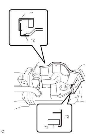
Text in Illustration *1 Front Exhaust Pipe Assembly *2 No. 2 Exhaust Pipe Heat Insulator Set the No. 2 exhaust pipe heat insulator on the front exhaust pipe assembly.
Note
Confirm that No. 2 exhaust pipe heat insulator is installed in the correct position.
-
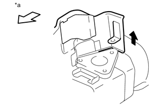
Text in Illustration *a Vehicle Front Lift the rear side of the No. 2 exhaust pipe heat insulator to allow the exhaust pipe gas control actuator sub-assembly to be installed below the flange on the No. 2 exhaust pipe heat insulator.
-
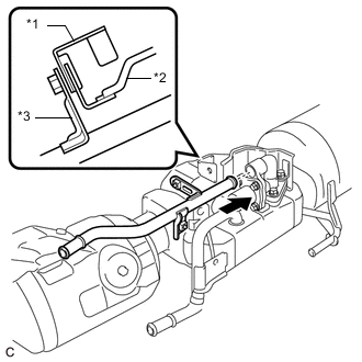
Text in Illustration *1 Front Exhaust Pipe Assembly *2 No. 2 Exhaust Pipe Heat Insulator *3 Exhaust Pipe Gas Control Actuator Sub-assembly *4 Pin Top Plate *5 Hook Set the exhaust pipe gas control actuator sub-assembly on the front exhaust pipe assembly as a set from the vehicle front.
-
Loosely install the 3 bolts several threads.
-
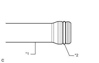
Text in Illustration *1 Exhaust By-pass Pipe *2 O-ring Apply clean engine coolant to the O-ring.
Note
Do not damage the O-ring or allow it to become contaminated with foreign matter during work.
-
Text in Illustration *1 Front Exhaust Pipe Assembly *2 No. 2 Exhaust Pipe Heat Insulator *3 Exhaust By-pass Pipe Install the exhaust by-pass pipe to the exhaust pipe gas control actuator sub-assembly.
Note
-
Make sure to insert the front exhaust pipe assembly into the exhaust pipe gas control actuator as far as possible.
-
Confirm that the front exhaust pipe assembly, exhaust by-pass pipe and No.2 exhaust pipe heat insulator are positioned correctly.
-
When reusing the exhaust by-pass pipe, inspect the O-ring.
-
If the O-ring has scratches or cuts, replace the exhaust by-pass pipe.
-
Make sure that the O-ring and the fitting section of the exhaust pipe gas control actuator sub-assembly are free of oil or foreign matter.
-
Do not touch the O-ring or fitting section of the exhaust pipe gas control actuator sub-assembly.
-
-
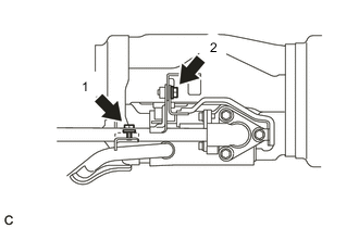
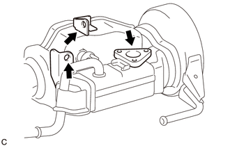
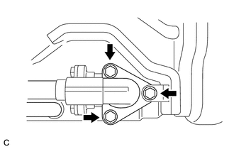
Install the 2 bolts in the order shown in the illustration.
- Torque:
- 8.5 N*m { 87 kgf*cm, 75 in.*lbf }
-
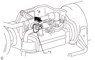
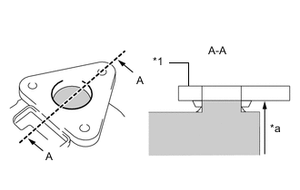
Text in Illustration *1 Valve Plate *a Insertion Direction Confirm that the valve plate is positioned correctly by pressing the plate.
Tech Tips
If the valve plate is not positioned correctly, the final exhaust pipe gas control actuator sub-assembly position may be difficult to achieve.
-
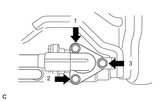
Tighten the 3 bolts in the order shown in the illustration in several steps.
- Torque:
- 5.0 N*m { 51 kgf*cm, 44 in.*lbf }
-
Adjust the installation position of the exhaust by-pass pipe.
-
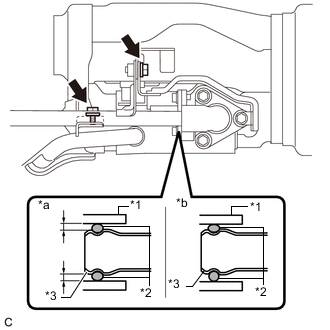
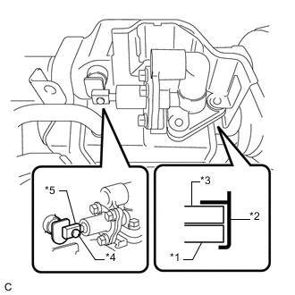
Text in Illustration *1 Exhaust Pipe Gas Control Actuator Sub-assembly *2 O-ring *3 Exhaust By-pass Pipe *a OK (O-ring is not deformed.) *b NG (O-ring is deformed.) Loosen the 2 bolts slightly.
Note
Do not remove these 2 bolts.
-
Move the exhaust by-pass pipe up and down to properly settle the O-ring.
Note
Make sure to settle the O-ring to distribute the pressure applied to the upper part of the O-ring. Failure to do so may cause engine coolant to leak.
-
-
Tighten the 2 bolts in the order shown in the illustration.
- Torque:
- 8.5 N*m { 87 kgf*cm, 75 in.*lbf }
-
When replacing the exhaust pipe gas control actuator sub-assembly with a new one:
-
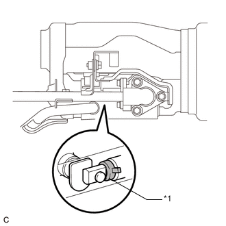
Text in Illustration *1 Spacer Remove the spacer from the new exhaust pipe gas control actuator sub-assembly.
Note
To prevent a malfunction of the exhaust pipe gas control actuator sub-assembly, the spacer must be removed.
Tech Tips
The spacer is provided with a new exhaust pipe gas control actuator sub-assembly.
-
-
-
INSTALL FRONT EXHAUST PIPE ASSEMBLY
-
ADD COOLANT (for Engine)
-
INSPECT FOR COOLANT LEAK (for Engine)
CAUTION:
Do not remove the radiator cap while the engine and radiator are still hot. Pressurized hot engine coolant and steam may be released and cause serious burns.
Tech Tips
Be sure to turn the A/C switch off before starting the following inspection.
-
Turn the power switch off. Check for engine coolant leaks from the front exhaust pipe assembly and the heater hose around the exhaust pipe gas control actuator sub-assembly.
-
Add engine coolant to the reserve tank and install a radiator cap tester.
-
Pump the cap tester to 118 kPa (1.2 kgf/cm2, 17 psi), and then check that the pressure does not drop.
If the reading drops, check for leaks from the front exhaust pipe assembly and the heater hose around the exhaust pipe gas control actuator sub-assembly.
-
Warm up the engine until the coolant temperature reaches the point that the exhaust pipe gas control actuator sub-assembly starts operating (80°C or more) and check for leaks
If external leaks are found, replace the exhaust pipe assembly.
-