ENGINE UNIT DISASSEMBLY
Note
-
When replacing the injectors (including shuffling the injectors between the cylinders), common rail or cylinder head, it is necessary to replace the injection pipes with new ones.
-
When replacing the fuel supply pump, common rail, cylinder block, cylinder head, cylinder head gasket or timing gear case, it is necessary to replace the fuel inlet pipe with a new one.
-
REMOVE OIL FILLER CAP SUB-ASSEMBLY
-
REMOVE NOZZLE HOLDER SEAL
-
Remove the 4 nozzle holder seals.
-
-
REMOVE CYLINDER HEAD COVER SUB-ASSEMBLY
Note
If the cylinder head cover is removed, replace the 4 No. 3 cylinder head cover gaskets with new ones.
-
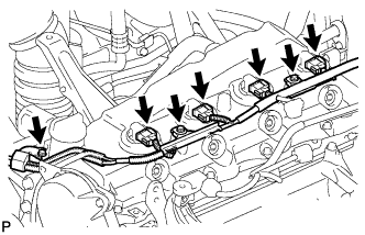
Remove the 3 bolts and disconnect the 4 connectors.
-
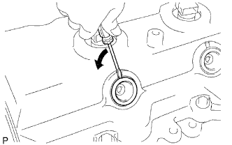
Using a small screwdriver, remove the holder seal by prying the portion between the holder seal and the cutout part of the cylinder head.
-
Disconnect the ventilation hose.
-
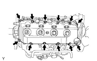
Remove the 10 bolts, 2 nuts, cylinder head cover and gasket.
-
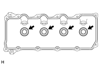
Remove the 4 No. 3 cylinder head cover gaskets from the cylinder head cover.
-
-
REMOVE CAMSHAFT TIMING PULLEY
-
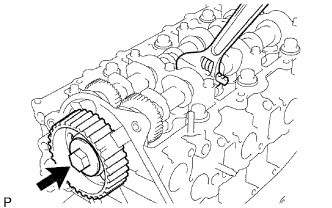
Remove the bolt of the camshaft timing pulley by holding the camshaft with a wrench.
Note
Make sure to remove the bolt of the camshaft timing pulley with the timing belt not installed.
-
Remove the camshaft timing pulley.
-
-
REMOVE NO. 2 TIMING BELT COVER
-
Remove the 4 bolts, nuts and No. 2 timing belt cover.
-
-
REMOVE CYLINDER BLOCK INSULATOR (w/ EGR Cooler)
-
Remove the cylinder block insulator from the cylinder head.
-
-
REMOVE INJECTOR ASSEMBLY
-
REMOVE CAMSHAFT
-
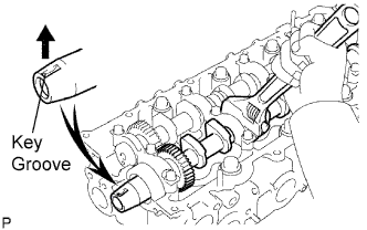
Face the key groove of the camshaft upward by turning the camshaft with a wrench.
-
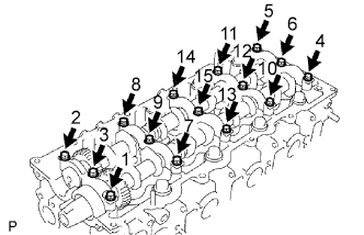
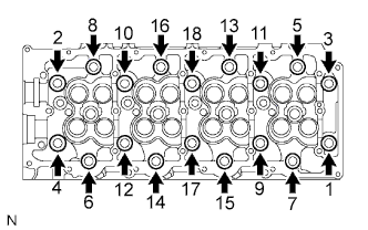
Uniformly loosen the 15 bearing cap bolts in several passes in the sequence shown in the illustration.
-
Remove the 5 bearing caps, oil seal and 2 camshafts.
-
-
REMOVE CYLINDER HEAD SUB-ASSEMBLY
-
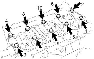
Uniformly loosen and remove the 18 cylinder head bolts in several passes in the sequence shown in the illustration.
Note
Head warpage or cracking could result from removing bolts in the incorrect order.
-
Lift the cylinder head from the dowels on the cylinder block, and place the cylinder head on wooden blocks on a bench.
Tech Tips
If the cylinder head is difficult to lift, use a screwdriver to pry between the cylinder head and block.
Note
Be careful not to damage the contact surfaces of the cylinder head and cylinder block.
-
-
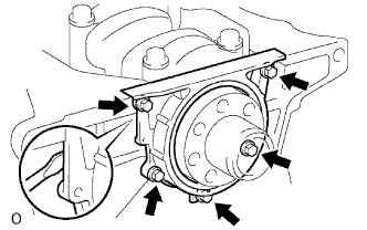
REMOVE WATER PUMP ASSEMBLY
-
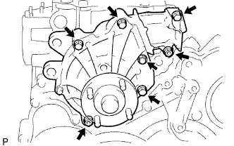
Remove the 5 bolts, 2 nuts, water pump and gasket.
-
-
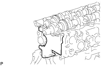
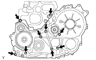
REMOVE TIMING GEAR CASE
-
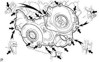
Remove the 14 bolts and 2 nuts.
-
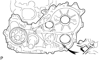
Pry the gear cover in the location shown in the illustration, and remove the gear cover together with the supply pump drive gear.
Note
Be careful not to drop the supply pump gear.
-
Remove the O-ring from the timing gear case.
-
-
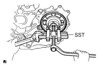
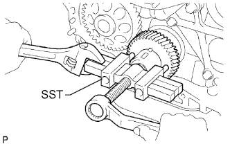
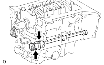
REMOVE SUPPLY PUMP GEAR
-
Using SST, remove the injection gear.
- SST
- 09950-50013 ( 09951-05010, 09952-05010, 09953-05020, 09954-05021 )
-
-
REMOVE NO. 1 CRANKSHAFT POSITION SENSOR PLATE
-
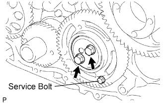
REMOVE NO. 1 IDLE GEAR
-
Secure the idle gears to the idle gear with the service bolt.
-
Remove the 2 bolts and thrust plate.
-
Turn the sub-gear and align the gear teeth of the idle main gear and sub-gear.
-
Remove the idle gear and sub-gear.
-
Remove the idle gear shaft.
-
-
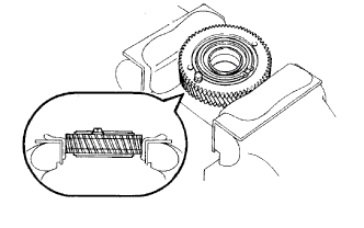
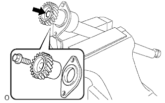
REMOVE NO. 1 IDLE SUB GEAR
-
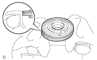
Mount the No. 1 idle gear and No. 2 idle sub-gear in a vise.
Note
Be careful not to damage the gears.
-
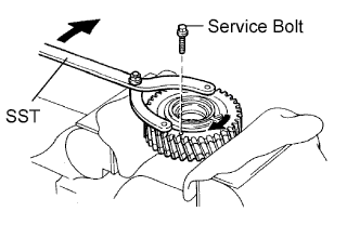
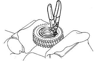
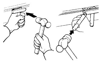
Using SST, turn the No. 1 idle sub-gear clockwise and remove the service bolt.
- SST
- 09960-10010 ( 09962-01000, 09963-00600 )
-
Using snap ring pliers, remove the shaft snap ring.
-
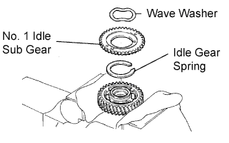
Remove the wave washer, sub-gear and gear spring.
-
-
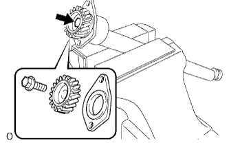
REMOVE NO. 2 IDLE SUB GEAR
-
Reverse the No. 1 idle gear and set it in a vise.
Note
Be careful not a damage the gear.
-
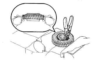
Using snap ring pliers, remove the shaft snap ring.
-
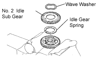
Remove the wave washer, sub-gear and gear spring.
-
-
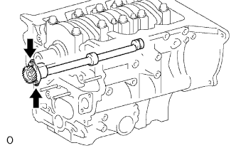
REMOVE CRANKSHAFT TIMING GEAR OR SPROCKET
-
Using SST, remove the crankshaft timing gear.
- SST
- 09950-50013 ( 09951-05010, 09952-05010, 09953-05010, 09954-05021 )
-
-
REMOVE OIL PAN SUB-ASSEMBLY
-
Remove the 4 bolts and oil level gauge sensor.
-
Remove the 22 bolts and 2 nuts.
-
Insert the blade of a oil pan seal cutter between the oil pan and cylinder block, cut through the applied sealer and remove the oil pan.
Note
-
Do not use a oil pan seal cutter for the timing belt case side and rear oil seal retainer.
-
Be careful not to damage the oil pan flange.
-
-
-
REMOVE OIL STRAINER SUB-ASSEMBLY
-
Remove the 2 bolts, 2 nuts, oil strainer and gasket.
-
-
REMOVE TIMING GEAR CASE ASSEMBLY
-
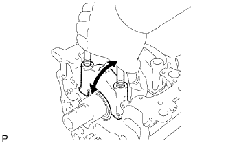
Remove the union bolt and 8 bolts.
-
Pry the gear case in the location shown in the illustration, and remove the gear case, driven rotor and gasket.
-
Remove the 2 O-rings.
-
-
REMOVE NO. 1 BALANCE SHAFT SUB-ASSEMBLY
-
Remove the 2 bolts and balance shaft.
-
-
REMOVE NO. 1 BALANCE SHAFT DRIVEN GEAR
-
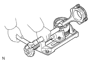
Mount the balance shaft between aluminum plates in a vise.
Note
Be careful not to damage the balance shaft.
-
Remove the bolt, balance shaft driven gear and balance shaft thrust washer.
-
-
REMOVE NO. 2 BALANCE SHAFT SUB-ASSEMBLY
-
Remove the 2 bolts and balance shaft.
-
-
REMOVE NO. 2 BALANCE SHAFT DRIVEN GEAR
-
Mount the balance shaft between aluminum plates in a vise.
Note
Be careful not to damage the balance shaft.
-
Remove the bolt, balance shaft driven gear and balance shaft thrust washer.
-
-
REMOVE ENGINE REAR OIL SEAL RETAINER
-
Remove the 5 bolts.
-
Using a screwdriver, remove the oil seal retainer by prying the portions between the oil seal retainer and cylinder block.
-
-
REMOVE CYLINDER BLOCK OIL ORIFICE
-
REMOVE PISTON AND CONNECTING ROD
-
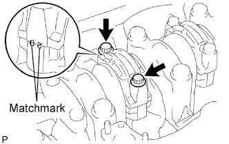
Check the matchmarks on the connecting rod and cap to ensure correct reassembly.
-
Remove the 2 connecting rod cap bolts.
-
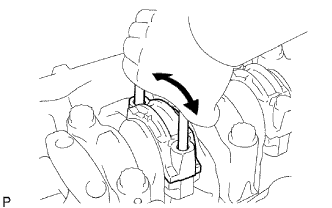
Using the 2 removed connecting rod bolts, pry the connecting rod cap back and forth, and remove the connecting cap.
Tech Tips
Keep the lower bearing inserted with the connecting rod cap.
-
Clean the crank pin and bearing.
-
Check the crank pin and bearing for pitting and scratches.
If the crank pin or bearing is damaged, replace the bearings. If necessary, grind or replace the crankshaft.
-
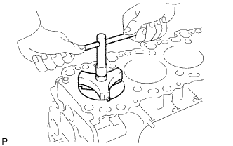
Using a ridge reamer, remove all the carbon from the top of the cylinder.
-
Push out the piston, connecting rod assembly and upper bearing through the top of the cylinder block.
Tech Tips
-
Keep the bearings, connecting rod and cap together.
-
Be sure to organize the removed piston and connecting rod assemblies in such a way that they can be reinstalled exactly as before.
-
-
-
REMOVE PISTON PIN
-
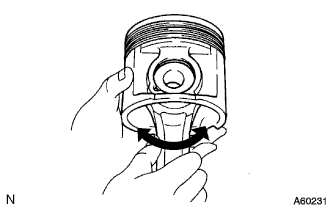
Check the fit between the piston pin and connecting rod.
-
Check that the piston moves smoothly.
If the piston does not move smoothly, replace the piston pin and connecting rod.
-
-
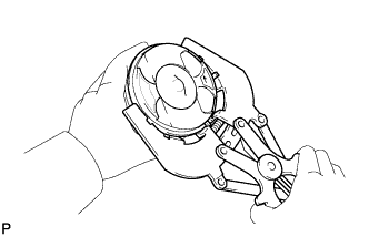
Using a piston ring expander, remove the 2 compression rings.
Tech Tips
Be sure to organize the removed piston rings in such a way that they can be reinstalled exactly as before.
-
Remove the coil and oil ring by hand.
-
Disconnect the connecting rod from the piston.
-
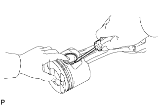
Using a small screwdriver, pry off the 2 snap rings from the piston.
-
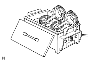
Gradually heat the piston to approximately 80°C (176°F).
-
Using plastic-face hammer and brass bar, lightly tap out the piston and pin. Then remove the connecting rod.
Tech Tips
-
The piston and pin are a matched set.
-
Be sure to organize the removed pistons, pins, rings, connecting rods and bearings in such a way that the parts can be reinstalled exactly as before.
-
-
-
-
REMOVE CRANKSHAFT SUB-ASSEMBLY
-
Uniformly loosen and remove the 10 crankshaft bearing cap bolts in several passes in the sequence shown.
-
Using the removed crankshaft bearing cap bolts, pry the cap back and forth, and remove the crankshaft bearing caps, lower crankshaft bearings and lower thrust washers (No. 3 crankshaft bearing cap only).
Tech Tips
-
Keep the lower crankshaft bearing and crankshaft bearings cap together.
-
Be sure to organize the bearing caps and lower thrust washers in such a way that they can be reinstalled exactly as before.
-
-
Lift out the crankshaft.
-
Remove the upper bearings and upper thrust washers from the cylinder block.
Tech Tips
Arrange the main bearing caps, bearings and thrust washers in the correct order.
-
-
REMOVE NO. 1 OIL NOZZLE SUB-ASSEMBLY
-
Remove the 4 check valves and oil nozzles.
-
-
REMOVE NO. 1 WITH HEAD STRAIGHT SCREW PLUG
-
Remove the screw plug and gasket.
-