CYLINDER BLOCK REPLACEMENT
PROCEDURE
-
REPLACE STRAIGHT PIN AND RING PIN
Note
It is not necessary to remove the straight pin and ring pin unless it is being replaced.
-
Using a plastic-faced hammer, tap in new straight pins and new ring pins to the cylinder block sub-assembly.
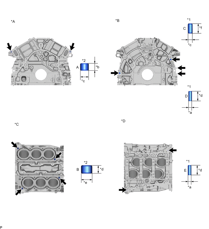
*A Front Side *B Rear Side *C Cylinder Block Sub-assembly Upper Side *D Cylinder Block Sub-assembly Lower Side *1 Straight Pin *2 Ring Pin *a 4 mm (0.157 in.) *b 8 mm (0.315 in.) *c 10 mm (0.394 in.) *d 12 mm (0.472 in.) *e 14 mm (0.551 in.) *f 22 mm (0.867 in.) Standard Protrusion Height Item Specified Condition A 3.0 to 5.0 mm (0.118 to 0.196 in.) B, D, E 5.0 to 7.0 mm (0.196 to 0.275 in.) C 10.0 to 12.0 mm (0.393 to 0.472 in.)
-