ELECTRONIC CONTROLLED AUTOMATIC TRANSMISSION SYSTEM (for 1KD-FTV), Diagnostic DTC:P0818
| DTC Code | DTC Name |
|---|---|
| P0818 | Driveline Disconnect Switch Input Circuit |
DESCRIPTION
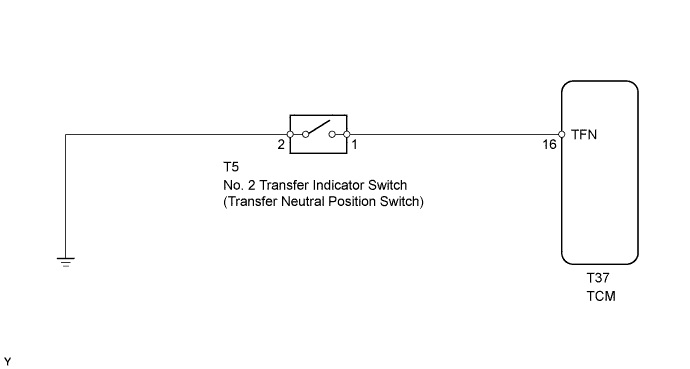
The TCM detects the signal from the transfer neutral position switch.
This DTC indicates that the transfer neutral position switch remains on.
| DTC No. | DTC Detection Condition | Trouble Area |
|---|---|---|
| P0818 | Transfer neutral position switch remains on while the vehicle is being driver under the following conditions for 30 sec. (2 trip detection logic):
|
|
MONITOR DESCRIPTION
The TCM detects whether or not the transfer shift lever is in neutral by monitoring the signal from the transfer neutral position switch.
If the TCM detects that the transfer shift lever is in neutral under all of the following conditions, the TCM will conclude that there is a malfunction of the transfer neutral position switch:
-
Transfer neutral position switch indicates that the transfer shift lever is in neutral.
-
Transfer shift lever is in the H position.
-
The vehicle is traveling at 25 km/h (16 mph) or more.
-
The transfer neutral position switch has been on for more than 30 seconds.
Then the TCM will illuminate the MIL and store the DTC.
WIRING DIAGRAM
INSPECTION PROCEDURE
PROCEDURE
-
CHECK HARNESS AND CONNECTOR (NO. 2 TRANSFER INDICATOR SWITCH - BODY GROUND)
-
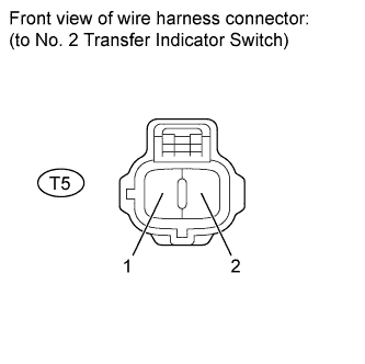
Disconnect the T5 switch connector.
-
Measure the resistance of the wire harness side connector.
Standard Resistance Transfer Connection Condition Specified Condition T5-2 - Body ground Always Below 1 Ω
NG 
REPAIR OR REPLACE HARNESS OR CONNECTOR
OK 
-
-
INSPECT NO. 2 TRANSFER INDICATOR SWITCH (TRANSFER NEUTRAL POSITION SWITCH)
-
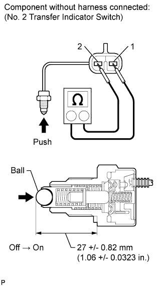
Remove the transfer indicator switch.
-
Measure the resistance of the switch when pushing the ball at the tip of the switch.
Standard Resistance Tester Connection Switch Condition Specified Condition 1 - 2 Not pushed 10 kΩ or higher 1 - 2 Pushed Below 1 Ω
NG
REPLACE NO. 2 TRANSFER INDICATOR SWITCH (TRANSFER NEUTRAL POSITION SWITCH)
OK
-
-
CHECK HARNESS AND CONNECTOR (NO. 2 TRANSFER INDICATOR SWITCH - TCM)
-
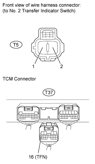
Disconnect the T5 switch connector.
-
Disconnect the T37 TCM connector.
-
Measure the resistance of the wire harness side connectors.
Standard Resistance Tester Connection Condition Specified Condition T5-1 - T37-16 (TFN) Always Below 1 Ω T37-16 (TFN) - Body ground Always 10 kΩ or higher
NG
REPAIR OR REPLACE HARNESS OR CONNECTOR
OK 
REPLACE TCM
-