ДАТЧИК ТЕМПЕРАТУРЫ ОТРАБОТАВШИХ ГАЗОВ (передний) УСТАНОВКА
-
INSTALL EXHAUST GAS TEMPERATURE SENSOR
-
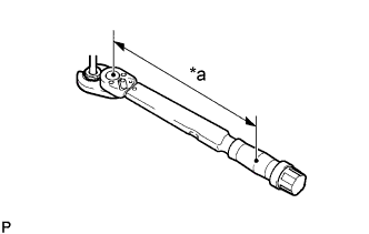
Text in Illustration *a Torque Wrench Fulcrum Length Using a 14 mm union nut wrench, install the No. 3 exhaust gas temperature sensor to the exhaust manifold converter sub-assembly.
Torque Specified tightening torque 30 N*m {306 kgf*cm, 22 ft.*lbf} Note
-
If the No. 3 exhaust gas temperature sensor is dropped, replace it with a new.
-
When reusing the No. 3 exhaust gas temperature sensors, clean the screws and apply anti-seize compound before installing the No. 3 exhaust gas temperature sensor.
Tech Tips
-
The connector color of the No. 3 exhaust gas temperature sensor is gray.
-
Calculate the torque wrench reading when changing the fulcrum length of the torque wrench Click here.
-
When using a union nut wrench (fulcrum length of 25 mm (0.984 in.)) + torque wrench (fulcrum length of 180 mm (7.09 in.)): 26 N*m (268 kgf*cm, 19 ft.*lbf)
-
-
Text in Illustration *a Torque Wrench Fulcrum Length Using a 14 mm union nut wrench, install the No. 2 exhaust gas temperature sensor to the exhaust manifold converter sub-assembly.
Torque Specified tightening torque 30 N*m {306 kgf*cm, 22 ft.*lbf} Note
-
If the No. 2 exhaust gas temperature sensor is dropped, replace it with a new.
-
When reusing the No. 2 exhaust gas temperature sensors, clean the screws and apply anti-seize compound before installing the No. 2 exhaust gas temperature sensor.
Tech Tips
-
The connector color of the No. 2 exhaust gas temperature sensor is black.
-
Calculate the torque wrench reading when changing the fulcrum length of the torque wrench Click here.
-
When using a union nut wrench (fulcrum length of 25 mm (0.984 in.)) + torque wrench (fulcrum length of 180 mm (7.09 in.)): 26 N*m (268 kgf*cm, 19 ft.*lbf)
-
-
Text in Illustration *a Torque Wrench Fulcrum Length Using a 14 mm union nut wrench, install the exhaust gas temperature sensor to the exhaust manifold converter sub-assembly.
Torque Specified tightening torque 30 N*m {306 kgf*cm, 22 ft.*lbf} Note
-
If the exhaust gas temperature sensor is dropped, replace it with a new.
-
When reusing the exhaust gas temperature sensors, clean the screws and apply anti-seize compound before installing the exhaust gas temperature sensor.
Tech Tips
-
The connector color of the exhaust gas temperature sensor is white.
-
Calculate the torque wrench reading when changing the fulcrum length of the torque wrench Click here.
-
When using a union nut wrench (fulcrum length of 25 mm (0.984 in.)) + torque wrench (fulcrum length of 180 mm (7.09 in.)): 26 N*m (268 kgf*cm, 19 ft.*lbf)
-
-
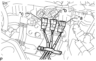
Text in Illustration *a White *b Black *c Gray Attach the 3 colored connectors to the pipe clamp in the positions shown in the illustration.
-
Close the clamp of the pipe clamp, and install the bolt.
- Torque:
- 10 N*m { 102 kgf*cm, 7 ft.*lbf }
Note
Arrange the exhaust gas temperature sensor wires so that they do not contact each other.
-
Connect the No. 3 exhaust gas temperature sensor to the No. 1 vacuum pipe.
- Torque:
- 10 N*m { 102 kgf*cm, 7 ft.*lbf }
-
Connect the 3 connectors to the 3 exhaust gas temperature sensors.
-
-
INSTALL ENGINE ASSEMBLY
Tech Tips
Perform this procedure only when removal or installation of the No. 3 exhaust gas temperature sensor.
-
INSTALL ENGINE SERVICE HOLE SUB COVER SUB-ASSEMBLY
-
Install the engine service hole sub cover sub-assembly with the 5 bolts.
- Torque:
- 13 N*m { 133 kgf*cm, 10 ft.*lbf }
-
Return the floor carpet to its original position.
-
-
INSTALL FRONT DOOR SCUFF PLATE RH
-
INSTALL FRONT SEAT ASSEMBLY RH
-
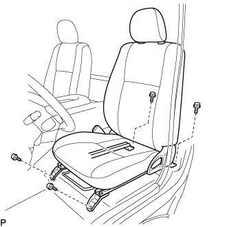
Подсоедините разъем замка ремня безопасности переднего сиденья в сборе и установите переднее сиденье в сборе.
-
Совместите штырь регулятора переднего сиденья в сборе с отверстиями в кузове.
-
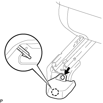
Сдвиньте переднее сиденье в сборе в крайнее заднее положение.
Note
Убедитесь, что переднее сиденье в сборе надежно зафиксировано.
-
Предварительно затяните 2 болта на передней стороне переднего сиденья в сборе.
-
Выдвиньте переднее сиденье в сборе до упора вперед.
Note
Убедитесь, что переднее сиденье в сборе надежно зафиксировано.
-
Предварительно затяните 2 болта на задней стороне переднего сиденья в сборе.
-
Сдвиньте переднее сиденье в сборе в крайнее заднее положение.
Note
Убедитесь, что переднее сиденье в сборе надежно зафиксировано.
-
Полностью затяните 2 болта на передней стороне переднего сиденья в сборе, сначала наружный, а затем внутренний.
- Torque:
- 39 Н*м { 398 кгс*см, 29 фунт-сила-футов }
-
Выдвиньте переднее сиденье в сборе до упора вперед.
Note
Убедитесь, что переднее сиденье в сборе надежно зафиксировано.
-
Полностью затяните 2 болта на задней стороне переднего сиденья в сборе, сначала наружный, а затем внутренний.
- Torque:
- 39 Н*м { 398 кгс*см, 29 фунт-сила-футов }
-
-
INSTALL SEAT TRACK COVER LH
-
Введите в зацепление захват и установите новый щиток направляющей левого сиденья и закрепите новым фиксатором.
-