СИСТЕМА ECD Starter Signal Circuit
DESCRIPTION
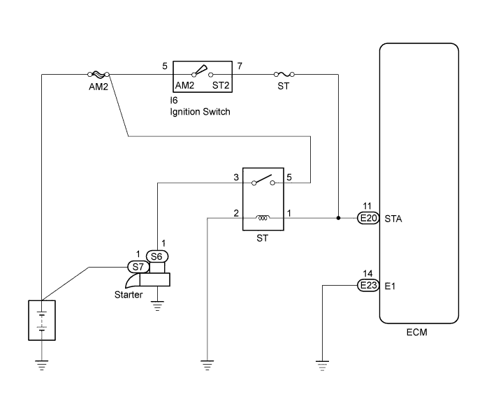
When the engine is cranked, the intake air flow becomes slow, so fuel vaporization is poor. A rich mixture is therefore necessary in order to achieve good startability. While the engine is being cranked, the battery voltage is applied to terminal STA of the ECM. The starter signal is mainly used to increase the fuel injection volume for starting and after-start injection control.
WIRING DIAGRAM
INSPECTION PROCEDURE
When using intelligent tester:
PROCEDURE
-
READ VALUE USING INTELLIGENT TESTER (STA SIGNAL)
-
Connect the intelligent tester to the DLC3.
-
Turn the ignition switch ON and turn the intelligent tester ON.
-
Enter the following menus: Powertrain / Engine and ECT / Data List / Starter Signal.
-
Read the STA signal on the intelligent tester while the starter operates.
Result Ignition Switch Position STA Signal LOCK, ACC, ON OFF STA ON
OK 
PROCEED TO NEXT CIRCUIT INSPECTION SHOWN IN PROBLEM SYMPTOMS TABLE
NG 
-
-
INSPECT FUSE (ST)
-
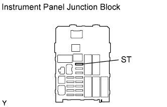
Remove the ST fuse from the instrument panel junction block.
-
Measure the resistance of the fuse.
Standard resistance Tester Connection Specified Condition ST fuse Below 1 Ω
NG
CHECK FOR SHORT IN ALL HARNESSES AND COMPONENTS CONNECTED TO FUSE, AND REPLACE FUSE
OK
-
-
CHECK WIRE HARNESS (IGNITION SWITCH - ST FUSE, ST FUSE - ECM)
-
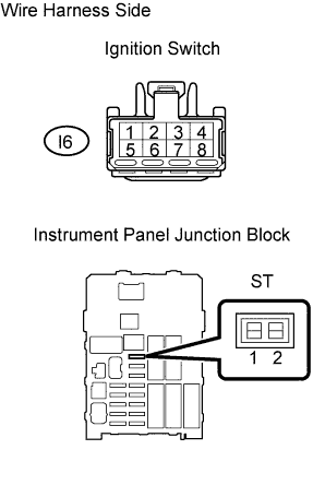
Check the wire harness between the ignition switch and ST fuse.
-
Disconnect the ignition switch connector.
-
Remove the ST fuse from the instrument panel junction block.
-
Measure the resistance of the wire harness side connectors.
Standard resistance Tester Connection Specified Condition I6-7 (ST2) - Instrument panel junction block ST fuse terminal 1 Below 1 Ω I6-7 (ST2) or Instrument panel junction block ST fuse terminal 1 - Body ground 10 kΩ or higher
-
-
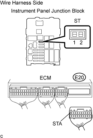
Check the wire harness between the ST fuse and ECM.
-
Remove the ST fuse from the instrument panel junction block.
-
Disconnect the E20 ECM connector.
-
Measure the resistance of the wire harness side connectors.
Standard resistance Tester Connection Specified Condition Instrument panel junction block ST fuse terminal 2 - E20-11 (STA) Below 1 Ω Instrument panel junction block ST fuse terminal 2 or E20-11 (STA) - Body ground 10 kΩ or higher
-
NG
REPAIR OR REPLACE HARNESS AND CONNECTOR
OK 
REPLACE ECM
-
When not using intelligent tester:
PROCEDURE
-
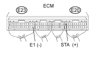
CHECK ECM (STA VOLTAGE)
-
Turn the ignition switch ON.
-
Measure the voltage of the ECM connector.
Standard voltage Tester Connection Condition Specified Condition E20-11 (STA) - E23-14 (E1) Cranking 6 V or more
OK
PROCEED TO NEXT CIRCUIT INSPECTION SHOWN IN PROBLEM SYMPTOMS TABLE
NG
-
-
INSPECT FUSE (ST)
-
Remove the ST fuse from the instrument panel junction block.
-
Measure the resistance of the ST fuse.
Standard resistance Tester Connection Specified Condition ST fuse Below 1 Ω
NG
CHECK FOR SHORT IN ALL HARNESSES AND COMPONENTS CONNECTED TO FUSE, AND REPLACE FUSE
OK
-
-
CHECK WIRE HARNESS (IGNITION SWITCH - ST FUSE, ST FUSE - ECM)
-
Check the wire harness between the ignition switch and ST fuse.
-
Disconnect the ignition switch connector.
-
Remove the ST fuse from the instrument panel junction block.
-
Measure the resistance of the wire harness side connectors.
Standard resistance Tester Connection Specified Condition I6-7 (ST2) - Instrument panel junction block ST fuse terminal 1 Below 1 Ω I6-7 (ST2) or Instrument panel junction block ST fuse terminal 1 - Body ground 10 kΩ or higher
-
-
Check the wire harness between the ST fuse and ECM.
-
Remove the ST fuse from the instrument panel junction block.
-
Disconnect the E20 ECM connector.
-
Measure the resistance of the wire harness side connectors.
Standard resistance Tester Connection Specified Condition Instrument panel junction block ST fuse terminal 2 - E20-11 (STA) Below 1 Ω Instrument panel junction block ST fuse terminal 2 or E20-11 (STA) - Body ground 10 kΩ or higher
-
NG
REPAIR OR REPLACE HARNESS AND CONNECTOR
OK
REPLACE ECM
-