ГЕНЕРАТОР ПРОВЕРКА
-
INSPECT GENERATOR W/ VACUUM PUMP ASSEMBLY
-
Mount the generator in a vise.
-
Insert the screwdriver to hold the generator rotor.
-
Hold the bolt and nut to the pulley.
-
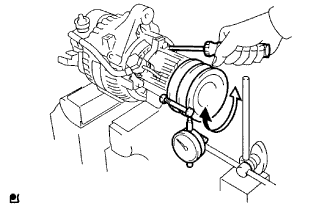
Set a dial indicator as shown in the illustration.
-
Turn the pulley and check the backlash between generator rotor and vacuum pump shaft.
Maximum backlash 1.6 mm If the backlash is greater than the maximum, replace the generator rotor and vacuum pump shaft.
-
-
INSPECT GENERATOR ROTOR ASSEMBLY
-
Check the rotor for an open circuit.
-
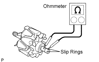
Using an ohmmeter, measure the resistance between the slip rings.
Standard resistance 2.1 to 2.5 Ω at 20°C (68°F) If the result is not as specified, replace the generator rotor assembly.
-
-
Check the rotor for a short circuit.
-
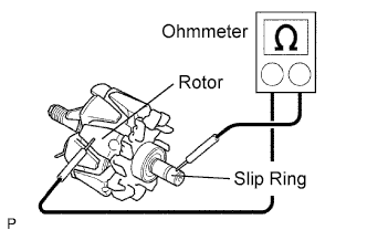
Using an ohmmeter, measure the resistance between the each slip ring and rotor.
Standard resistance 10 kΩ or higher If the result is not as specified, replace the generator rotor assembly.
-
-
Check that the slip rings are not rough or scored.
If they are rough or scored, replace the rotor.
-
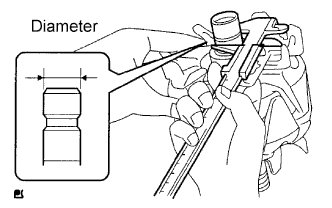
Using vernier calipers, measure the slip ring diameter.
Standard diameter 14.2 to 14.4 mm (0.559 to 0.567 in.) Minimum diameter 12.8 mm (0.504 in.) If the diameter is less than the minimum, replace the rotor assembly.
-
Inspect the bearing.
-
Check if the bearing is not rough or worn.
If necessary, replace the generator rotor.
-
-
-
INSPECT DRIVE END FRAME
-
Check the stator for an open circuit.
-
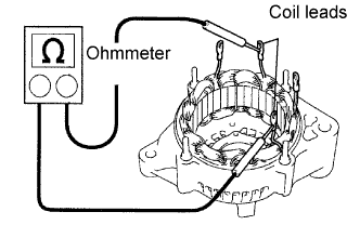
Using an ohmmeter, measure the resistance between the coil leads.
Standard resistance Below 1 Ω Tech Tips
If the result is not as specified, replace the drive end frame assembly.
-
-
Check the stator for a short circuit.
-
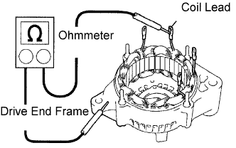
Using an ohmmeter, measure the resistance between the each coil lead and drive end frame assembly.
Standard resistance 10 kΩ or higher Tech Tips
If the result is not as specified, replace the drive end frame assembly.
-
-
Inspect the bearing.
-
Check if the bearing is not rough or worn.
If necessary, replace the drive end frame assembly.
-
-
-
INSPECT BRUSH HOLDER
-
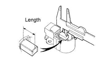
Using vernier calipers, measure the exposed brush length.
Standard exposed length 9.5 to 11.5 mm (0.374 to 0.453 in.) Minimum exposed length 1.5 mm (0.059 in.) If the exposed length is less than the minimum, replace the brush holder.
-
-
INSPECT GENERATOR HOLDER W/ RECTIFIER
-
Check the positive terminal of the rectifier.
-
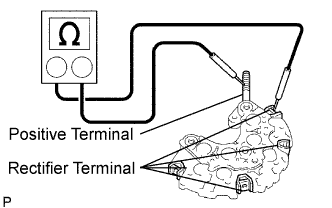
Using an ohmmeter, connect one tester probe to the positive terminal and the other to each rectifier terminal.
-
Reverse the polarity of the tester probes and repeat step (1).
-
Check that one shows continuity and the other shows no continuity.
Check that there is continuity one way but no continuity the other way.
-
-
Check the negative terminal of the rectifier.
-
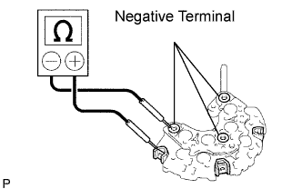
Using an ohmmeter, connect one tester probe to each negative terminal and the other to each rectifier terminal.
-
Reverse the polarity of the tester probes and repeat step (1).
-
Check that there is continuity one way but no continuity the other way.
If the continuity is not as specified, replace the generator holder w/ rectifier.
-
-
-
INSPECT REGULATOR
-
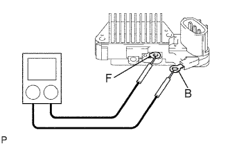
Using an ohmmeter, check the continuity between terminals F and B.
Standard When the positive and negative poles between terminals F and B are exchanged, there is continuity in one way but no continuity the other way. If the continuity is not as standard, replace the regulator. -
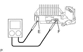
Using an ohmmeter, check the continuity between terminals F and E.
Standard When the positive and negative poles between terminals F and E are exchanged, there is continuity in one way but no continuity the other way. If the continuity is not as standard, replace the regulator.
-