CLUTCH STROKE SENSOR(for EC65A) INSPECTION
PROCEDURE
INSPECT CLUTCH STROKE SENSOR
-
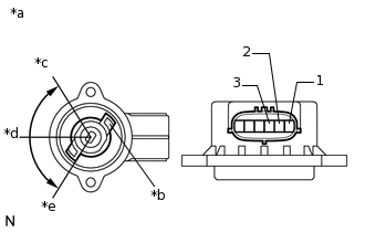
*a
Main Circuit
*b
Sensor Arm
*c
55°
*d
0°
*e
-55°
Check the voltage between the terminals of the clutch stroke sensor connector (main circuit).
Prepare 3 dry cell batteries (1.5 V) and 2 leads for connecting the batteries and the sensor.
Connect the batteries in series.
Connect a positive (+) lead from the battery to sensor terminal 3, and a negative (-) lead to sensor terminal 2.
Measure the voltage according to the values in the table below.
Standard Voltage (combined dry cell battery voltage of 4.5 V)
Sensor Angle
Terminal (1-2) Output Voltage
55°
Approximately 4.05 V
0°
Approximately 2.25 V
-55°
Approximately 0.45 V
Reference Voltage (5.0 +/- 0.3 V)
Sensor Angle
Terminal (1-2) Output Voltage
55°
Approximately 4.5 V
0°
Approximately 2.5 V
-55°
Approximately 0.5 V
Note:Do not apply more than 6 V.
Do not use a sensor which has been dropped.
If the voltage is not as specified, replace the clutch stroke sensor.
-
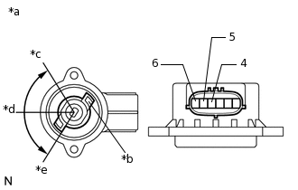
*a
Sub Circuit
*b
Sensor Arm
*c
55°
*d
0°
*e
-55°
Check the voltage between the terminals of the clutch stroke sensor connector (sub circuit).
Prepare 3 dry cell batteries (1.5 V) and 2 leads for connecting the batteries and the sensor.
Connect the batteries in series.
Connect a positive (+) lead from the battery to sensor terminal 6, and a negative (-) lead to sensor terminal 5.
Measure the voltage according to the values in the table below.
Standard Voltage (combined dry cell battery voltage of 4.5 V)
Sensor Angle
Terminal (4-5) Output Voltage
55°
Approximately 4.05 V
0°
Approximately 2.25 V
-55°
Approximately 0.45 V
Reference Voltage (5.0 +/- 0.3 V)
Sensor Angle
Terminal (4-5) Output Voltage
55°
Approximately 4.5 V
0°
Approximately 2.5 V
-55°
Approximately 0.5 V
Note:Do not apply more than 6 V.
Do not use a sensor which has been dropped.
If the voltage is not as specified, replace the clutch stroke sensor.
-