EGR COOLER INSTALLATION
PROCEDURE
INSTALL STUD BOLT
Tip:If a stud bolt is deformed or the threads are damaged, replace it.
Using an E8 "TORX" socket wrench, install the 2 stud bolts to the EGR pipe with cooler sub-assembly.
8.0 N*m
82 kgf*cm
71 in.*lbf
INSTALL NO. 2 EGR VALVE ASSEMBLY
Install a new gasket and the No. 2 EGR valve assembly to the EGR pipe with cooler sub-assembly.
Tip:Make sure that the claw of the gasket is facing the EGR pipe with cooler sub-assembly.
INSTALL NO. 1 EGR PIPE SUB-ASSEMBLY
Install a new gasket to the No. 2 EGR valve assembly.
Temporarily install the No. 1 EGR pipe sub-assembly with the 2 bolts and 2 nuts.
Tip:Tighten the bolts and nuts until there is no gap between the No. 1 EGR pipe sub-assembly, No. 2 EGR valve assembly and EGR pipe with cooler sub-assembly.
INSTALL EGR PIPE WITH COOLER SUB-ASSEMBLY
Install a new O-ring to the EGR pipe with cooler sub-assembly.
Install a new gasket to the EGR pipe with cooler sub-assembly and a new gasket to the No. 1 EGR pipe sub-assembly.
Temporarily install the EGR pipe with cooler sub-assembly with the 6 bolts and 2 nuts.
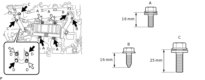

Bolt

Nut
Bolt Length
Item
Specified Condition
Bolt A
16 mm (0.630 in.)
Bolt B
16 mm (0.630 in.)
Bolt C
25 mm (0.984 in.)
Tighten the 2 bolts (A) and 2 nuts (A) shown in the illustration.
10 N*m
102 kgf*cm
7 ft.*lbf
Tighten the 2 bolts (B) shown in the illustration.
16 N*m
163 kgf*cm
12 ft.*lbf
Tighten the 2 bolts (C) shown in the illustration.
24 N*m
245 kgf*cm
18 ft.*lbf
Tighten the 2 bolts (D) and 2 nuts (D) shown in the illustration.
21 N*m
214 kgf*cm
15 ft.*lbf
Connect the vacuum hose.
INSTALL NO. 2 WATER BY-PASS HOSE
Install the No. 2 water by-pass hose, and slide the 2 clips to secure it.
INSTALL EXHAUST MANIFOLD CONVERTER SUB-ASSEMBLY