WATER PUMP REMOVAL

-
RECOVER REFRIGERANT FROM REFRIGERATION SYSTEM (w/ Air Conditioning System)
-
Start up the engine.
-
Turn the A/C switch on.
-
Operate the cooler compressor at an engine rpm of approximately 1,000 for 5 to 6 minutes to circulate the refrigerant and collect compressor oil remaining in each component into the cooler compressor as much as possible.
-
Stop the engine.
-
Using SST, let the refrigerant gas out.
- SST
- 07110-58060 ( 07117-58080, 07117-58090, 07117-78050, 07117-88060, 07117-88070, 07117-88080 )
-
-
DISCONNECT CABLE FROM NEGATIVE BATTERY TERMINAL
-
REMOVE NO. 1 ENGINE UNDER COVER (for Cold Area Specification Vehicles)
-
Remove the 4 bolts and No. 1 engine under cover.
-
-
DRAIN ENGINE COOLANT
CAUTION:
Do not remove the radiator reservoir cap sub-assembly while the engine and radiator are still hot. Pressurized, hot engine coolant and steam may be released and cause serious burns.
-
Loosen the radiator drain cock plug.
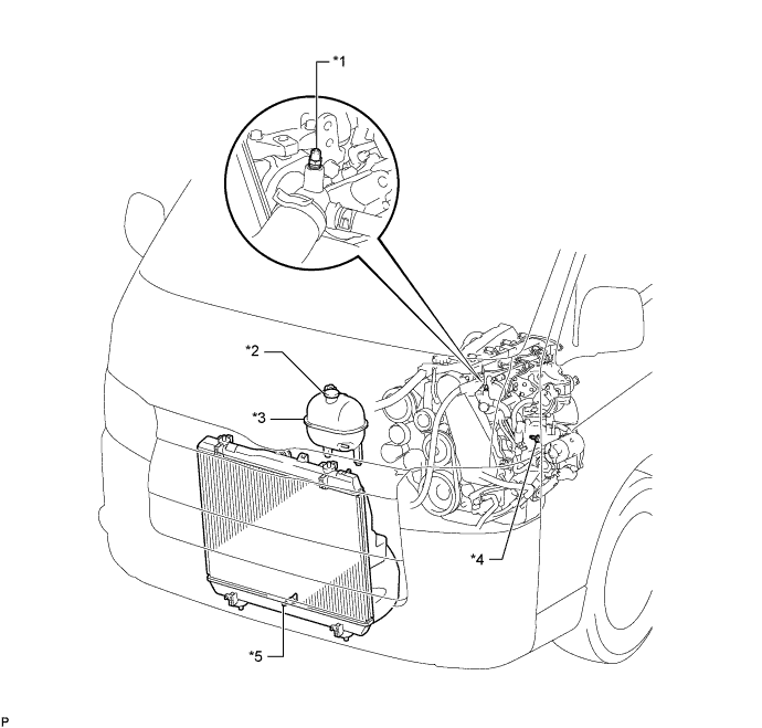
Text in Illustration *1 Bleeder Plug *2 Radiator Reservoir Cap Sub-assembly *3 Radiator Reservoir Assembly *4 Cylinder Block Drain Cock Plug *5 Radiator Drain Cock Plug - - -
Remove the radiator reservoir cap sub-assembly.
-
Loosen the cylinder block drain cock plug (on the engine oil cooler cover), and drain the engine coolant.
-
Tighten the radiator drain cock plug.
-
Tighten the cylinder block drain cock plug (on the engine oil cooler cover).
- Torque:
- 8.0 N*m { 82 kgf*cm, 71 in.*lbf }
-
-
REMOVE FRONT DOOR SCUFF PLATE RH
-
Disengage the 5 clips and remove the front door scuff plate RH.
-
-
REMOVE FRONT SEAT ASSEMBLY RH
-
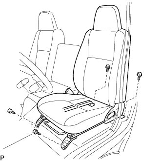
Move the front seat assembly fully forward.
-
Remove the 2 bolts on the rear side of the seat.
-
Move the front seat assembly to the rearmost position.
-
Remove the 2 bolts on the front side of the seat.
-
Move the front seat assembly to the center of the seat slide rail. Set the seatback in the upright position.
-
Disconnect the front seat inner belt assembly connector.
-
Remove the front seat assembly.
-
-
REMOVE ENGINE SERVICE HOLE SUB COVER SUB-ASSEMBLY
-
Roll up the carpet and remove the engine service hole sub cover.
-
-
REMOVE NO. 2 ENGINE SERVICE HOLE COVER
-
Detach the clips and fold back the carpet.
-
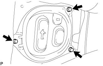
Remove the 3 bolts and No. 2 engine service hole cover.
-
-
REMOVE FENDER APRON MUDGUARD SEAL RH
-
Disengage the 3 clips and remove the fender apron mudguard seal RH.
-
-
REMOVE NO. 1 RADIATOR HOSE
-
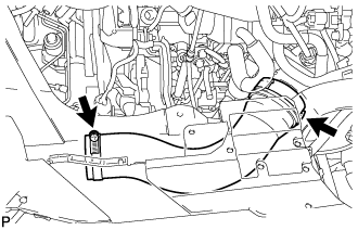
DISCONNECT VANE PUMP OIL RESERVOIR ASSEMBLY
-
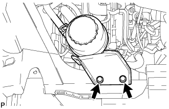
Remove the 2 bolts and disconnect the vane pump oil reservoir.
-
-
LOOSEN FAN PULLEY
-
Loosen the 4 nuts from the fan pulley.
-
-
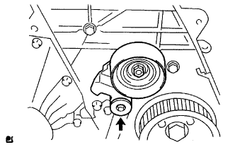
REMOVE FAN AND GENERATOR V BELT
-
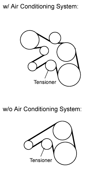
Remove the drive belt by rotating the tensioner pulley clockwise to loosen its tension with the pulley set bolt of the tensioner.
-
-
REMOVE FAN PULLEY
-
Remove the 4 nuts and fan pulley.
-
-
DISCONNECT NO. 1 AIR CLEANER HOSE
-
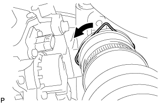
Pull the stopper upward and disconnect the No. 1 air cleaner hose from the compressor inlet elbow.
-
-
REMOVE AIR TUBE ASSEMBLY
-
Loosen the 2 hose clamps.
-
Remove the 2 bolts, air tube assembly and No. 1 air cleaner hose.
-
-
REMOVE COMPRESSOR OUTLET ELBOW
-
Loosen the 2 hose clamps and remove the bolt and compressor outlet elbow.
-
-
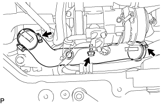
DISCONNECT NO. 1 COOLER REFRIGERANT DISCHARGE HOSE (w/ Air Conditioning System)
-
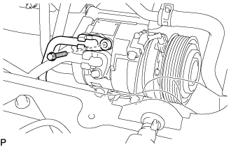
Remove the bolt and disconnect the cooler refrigerant discharge hose from the compressor and magnetic clutch.
-
Remove the O-ring from the cooler refrigerant discharge hose.
Note
Seal the openings of the disconnected parts using vinyl tape to prevent moisture and foreign matter from entering.
-
-
DISCONNECT NO. 1 COOLER REFRIGERANT SUCTION HOSE (w/ Air Conditioning System)
-
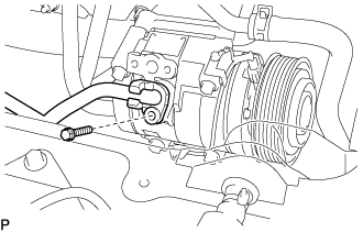
Remove the bolt and disconnect the cooler refrigerant suction hose.
-
Remove the O-ring from the cooler refrigerant suction hose.
Note
Seal the openings of the disconnected parts using vinyl tape to prevent moisture and foreign matter from entering.
-
-
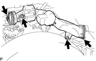
REMOVE COMPRESSOR AND MAGNETIC CLUTCH (w/ Air Conditioning System)
-
Disconnect the connector.
-
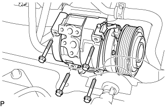
Remove the 4 bolts and compressor and magnetic clutch.
-
-
REMOVE NO. 1 COMPRESSOR MOUNTING BRACKET (w/ Air Conditioning System)
-
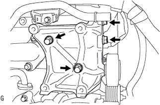
Remove the 4 bolts and No. 1 compressor mounting bracket.
-
-
REMOVE NO. 2 IDLE PULLEY ASSEMBLY (w/ Air Conditioning System)
-
Remove the bolt, pulley plate, No. 2 idle pulley and spacer.
-
-
REMOVE GENERATOR BRACKET
-
Remove the 2 bolts, then remove the generator bracket.
-
-
REMOVE GENERATOR ASSEMBLY
-
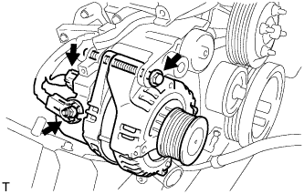
Disconnect the generator connector.
-
Remove the terminal cap.
-
Remove the nut and disconnect the wire harness from terminal B.
-
Remove the bolt and generator.
-
-
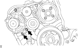
REMOVE V-RIBBED BELT TENSIONER ASSEMBLY
-
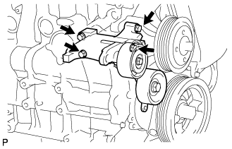
Remove the 4 bolts and V-ribbed belt tensioner.
-
-
REMOVE NO. 1 TIMING BELT COVER
-
Remove the wire harness clamp.
-
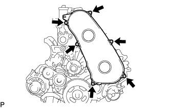
Remove the 6 bolts, 6 washers and timing belt cover.
-
-
REMOVE TIMING BELT
-
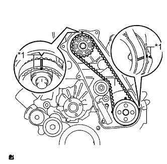
Text in Illustration *1 Timing Mark Turn the crankshaft clockwise and align the timing marks as shown in the illustration.
Tech Tips
If reusing the timing belt, place matchmarks on the timing belt so that it can be installed exactly as before.
-
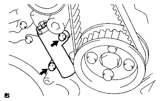
Uniformly loosen and remove the 2 bolts and No. 1 timing belt tensioner.
-
Remove the timing belt.
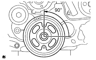
Tech Tips
-
If turning the camshaft while the timing belt is removed, turn the crankshaft 90° counterclockwise as shown in the illustration.
-
When installing the timing belt, turn the camshaft to align the timing marks, and then turn the crankshaft clockwise to align the timing marks.
-
-
-
REMOVE NO. 4 AIR HOSE (w/ DPF)
-
Loosen the 2 hose clamps.
-
Remove the No. 4 air hose.
-
-
REMOVE DIESEL THROTTLE BODY ASSEMBLY (w/ DPF)
-
w/o DPF:
-
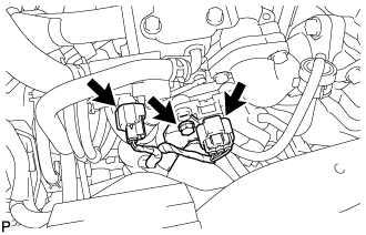
Disconnect the diesel turbo pressure sensor connector and vacuum switching valve connector.
-
Remove the bolt and disconnect the wire harness clamp.
-
-
Disconnect the 2 diesel throttle body connectors.
-
Remove the 2 bolts, 2 nuts, diesel throttle body and gasket.
-
-
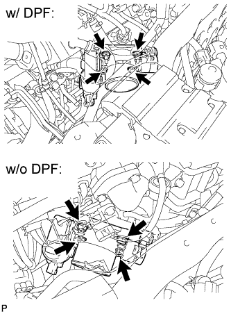
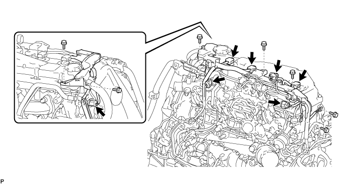
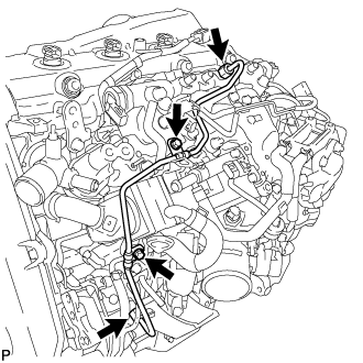
DISCONNECT ENGINE WIRE (w/ DPF)
-
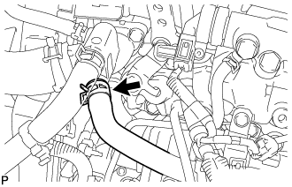
Detach the 3 clamps and disconnect the water by-pass hose and oil return hose.
-
Detach the clamp and disconnect the glow plug connector.
-
Detach the clamp and disconnect the engine wire from the No. 1 timing belt cover.
-
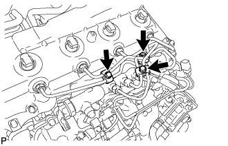
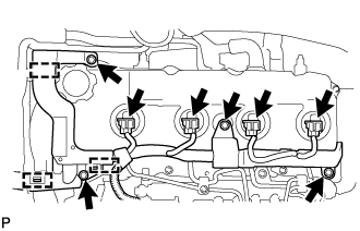
Disconnect the 7 connectors.
-
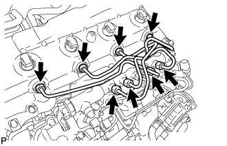
Remove the 7 bolts and disconnect the engine wire.
-
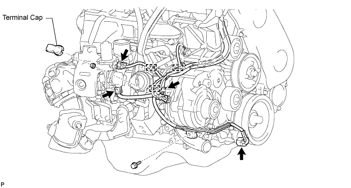
Disconnect the 4 connectors and detach the 3 clamps.
-
Remove the terminal cap.
-
Remove the nut and disconnect the generator wire from terminal B.
-
Remove the bolt and disconnect the engine wire.
-
Fold back the floor carpet.
-
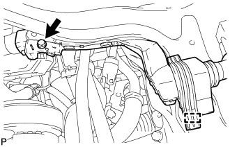
Remove the bolt.
-
Detach the clamp.
-
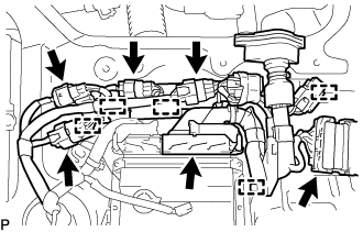
Disconnect the ECM connector Click here.
-
Disconnect the 5 connectors.
-
Detach the 5 clamps.
-
-
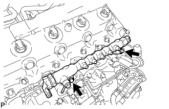
REMOVE INJECTION PIPE SUB-ASSEMBLY (w/ DPF)
-
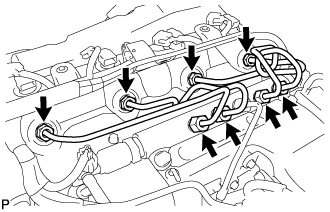
Remove the 3 bolts and 3 No. 2 injection pipe clamps.
-
Using a 17 mm union nut wrench, loosen the union nuts and remove the 4 injection pipes.
-
-
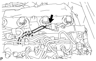
REMOVE VACUUM CONTROL VALVE SET (w/ DPF)
-
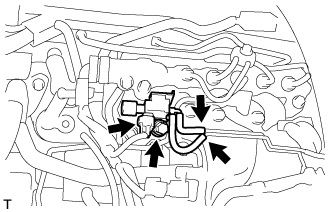
Disconnect the vacuum control valve connector and 2 vacuum hoses from the No. 3 vacuum transmitting pipe sub-assembly.
-
Remove the bolt and vacuum control valve set.
-
-
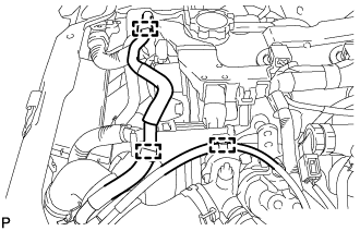
DISCONNECT NO. 5 WATER BY-PASS HOSE (w/ DPF)
-
REMOVE FUEL INLET PIPE SUB-ASSEMBLY (w/ DPF)
Note
If a No. 1 injection pipe clamp is removed from the fuel inlet pipe, replace the No. 1 injection pipe clamp with a new one.
-
Remove the 2 bolts and 2 No. 1 injection pipe clamps.
-
Using a 17 mm union nut wrench, loosen the union nuts and remove the fuel inlet pipe.
-
-
REMOVE COMMON RAIL ASSEMBLY (w/ DPF)
-
Remove the 2 bolts and common rail.
Note
Do not remove the pressure discharge valve or fuel pressure sensor.
-
-
REMOVE NO. 1 INTAKE MANIFOLD INSULATOR (w/ DPF)
-
REMOVE NO. 1 CYLINDER HEAD COVER SILENCER (w/ DPF)
-
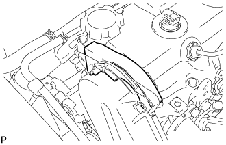
Remove the No. 1 cylinder head cover silencer from the cylinder head cover.
-
-
REMOVE INJECTION PIPE SUB-ASSEMBLY (w/o DPF)
-
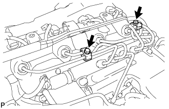
Disconnect the 4 injector connectors.
-
Remove the 4 bolts and detach the 3 clamps.
-
Remove the 2 bolts and 2 No. 2 injection pipe clamps.
-
Using a 17 mm union nut wrench, loosen the union nuts and remove the 4 injection pipes.
-
-
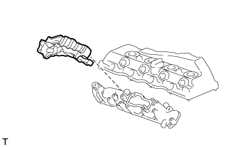
REMOVE CYLINDER HEAD COVER SUB-ASSEMBLY
-
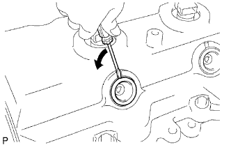
Using a small screwdriver, remove the nozzle holder seal by prying between the nozzle holder seal and the cutout part of the cylinder head cover.
-
Disconnect the ventilation hose.
-
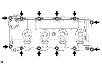
Remove the 10 bolts, 2 nuts, cylinder head cover and the cylinder head cover gasket.
-
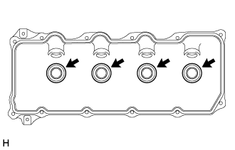
Remove the 4 No. 3 cylinder head cover gaskets from the cylinder head cover.
-
-
REMOVE NO. 1 TIMING BELT IDLER SUB-ASSEMBLY
-
Using a 10 mm hexagon wrench, remove the bolt, No. 1 timing belt idler and washer.
-
-
REMOVE CAMSHAFT TIMING PULLEY
-
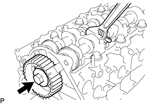
Remove the bolt and camshaft timing pulley while holding the camshaft with a wrench.
-
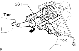
Using SST, remove the camshaft timing pulley and set key.
- SST
- 09950-40011 ( 09951-04010, 09952-04010, 09953-05010, 09957-04010 )
- 09955-04150
-
Rotate the crankshaft approximately 90° counterclockwise from TDC to lower the piston.
-
-
REMOVE NO. 2 TIMING BELT COVER
-
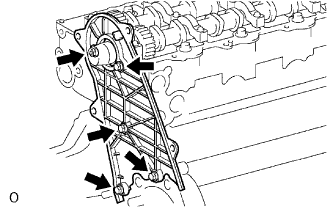
Remove the nut, 4 bolts and No. 2 timing belt cover.
-
-
REMOVE WATER PUMP ASSEMBLY
-
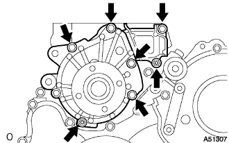
Remove the 5 bolts, 2 nuts and water pump assembly.
-