DYNAMIC REAR STEERING SYSTEM, Diagnostic DTC:C1B29
| DTC Code | DTC Name |
|---|---|
| C1B29 | IG Power Supply Voltage Circuit |
DESCRIPTION
When the DRS ECU (rear steering control ECU) detects a problem with the IG power source circuit, DTC C1B29 is stored.
| DTC No. | Detection Item | DTC Detection Condition | Trouble Area | Warning Indicate | Return-to-normal Condition |
|---|---|---|---|---|---|
| C1B29 | IG Power Supply Voltage Circuit | All conditions are met:
|
|
Comes on | Engine switch on (IG) again |
| Vehicle Condition | ||||||
|---|---|---|---|---|---|---|
| Pattern 1 | Pattern 2 | Pattern 3 | Pattern 4 | Pattern 5 | ||
| Diagnosis Condition | Engine switch is on (IG) | ○ | ○ | ○ | ○ | ○ |
| Malfunction Status | IG voltage is 4 V or less | ○ | - | - | - | - |
| IG voltage is 18.5 V or higher | - | - | - | ○ | - | |
| An open in the IG circuit | - | ○ | - | - | - | |
| A short in the IG circuit | - | - | - | - | ○ | |
| An internal malfunction in the ECU | - | - | ○ | - | - | |
| Detection Time | Approximately 3 seconds or more | Approximately 3 seconds or more | Approximately 3 seconds or more | Approximately 3 seconds or more | Approximately 3 seconds or more | |
| Number of Trips | 1 trip | 1 trip | 1 trip | 1 trip | 1 trip | |
Tech Tips
DTC will be output when conditions for either of the patterns in the table above are met.
WIRING DIAGRAM
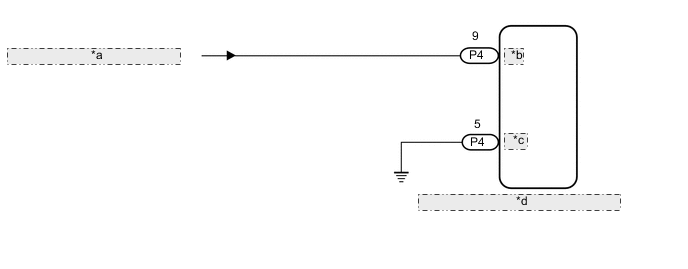
| *a | from Engine Stop and Start ECU |
| *b | IGY |
| *c | GNDY |
| *d | DRS ECU (Rear Steering Control ECU) |
CAUTION / NOTICE / HINT
Note
-
When replacing the DRS ECU (rear steering control ECU), perform neutral position memorization and motor rotation angle sensor calibration.
-
Since DTC C1597 is stored in the VGRS ECU (front steering control ECU), after performing repairs on the dynamic rear steering system, clear the DTCs for the VGRS system.
-
When this troubleshooting procedure is performed, DTCs indicating a CAN communication malfunction with the DRS ECU (rear steering control ECU) are stored in other ECUs. Therefore, after performing repairs on the dynamic rear steering system, clear DTCs.
-
Before performing troubleshooting, turn off the remote service function.
PROCEDURE
-
READ VALUE USING GTS (IG POWER SUPPLY VOLTAGE)
-
Turn the engine switch off.
-
Connect the GTS to the DLC3.
-
Turn the engine switch on (IG).
-
Turn the GTS on.
-
Enter the following menus: Chassis / DRS / Data List.
Chassis > DRS > Data ListTester Display Measurement Item Range Normal Condition Diagnostic Note IG Power Supply Voltage IG power supply voltage Min.: 0.00 V
Max.: 255.99 V
10.5 to 16 V -
Chassis > DRS > Data ListTester Display IG Power Supply Voltage Result Result Proceed to Below 10.5 V A 10.5 to 16 V B Higher than 16 V C
B 
USE SIMULATION METHOD TO CHECK Click here
C
REPLACE DRS ECU (REAR STEERING CONTROL ECU) Click here
A 
-
-
CHECK HARNESS AND CONNECTOR (GNDY - BODY GROUND)
-
Turn the engine switch off.
-
Disconnect the P4 DRS ECU (rear steering control ECU) connector.
-
Measure the resistance according to the value(s) in the table below.
Standard Resistance Tester Connection Condition Specified Condition P4-5 (GNDY) - Body ground Always Below 1 Ω Result Proceed to OK NG
NG
REPAIR OR REPLACE HARNESS OR CONNECTOR
OK
-
-
CHECK HARNESS AND CONNECTOR (IGY - BODY GROUND)
-
Turn the engine switch on (IG).
-
Measure the voltage according to the value(s) in the table below.
Tech Tips
With the connector connected to the VGRS ECU (front steering control ECU), measure the voltage from the rear of the connector.
Standard Voltage Tester Connection Condition Specified Condition P4-9 (IGY) - Body ground Engine switch on (IG) 10.5 to 16 V Result Proceed to OK NG
OK
REPLACE DRS ECU (REAR STEERING CONTROL ECU) Click here
NG
GO TO STOP AND START SYSTEM (BACKUP BOOST CONVERTER CIRCUIT) Click here
-