DIFFERENTIAL CARRIER ASSEMBLY (for DANA Made) REASSEMBLY
-
INSTALL DIFFERENTIAL RING GEAR
-
Clean the contact surfaces of the differential case and ring gear.
-
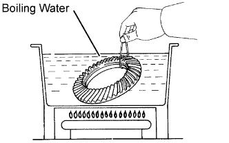
Heat the ring gear in boiling water that is approximately 100°C (212°F).
-
Carefully remove the ring gear from the boiling water.
-
After the moisture on the ring gear has completely evaporated, quickly install the ring gear to the differential case.
-
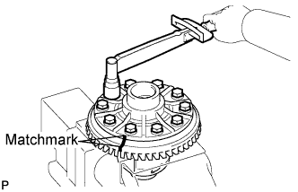
Align the matchmarks on the ring gear with those of the differential case.
-
Temporarily install the 10 bolts.
-
After the ring gear cools down, uniformly tighten the 10 bolts in diametrically opposite pairs in several passes.
- Torque:
- 160 to 180 N*m { 1,632 to 1835 kgf*cm, 118 to 133 ft.*lbf }
-
-
INSTALL REAR DIFFERENTIAL CASE BEARING
-
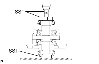
Using SST and a press, press the bearing onto the differential case.
- SST
- 09950-60010 ( 09951-00430, 09951-00480, 09951-00470, 09951-00550 )
- 09950-70010 ( 09951-07150, 09951-00560, 09951-00570 )
-
-
INSPECT DIFFERENTIAL RING GEAR RUNOUT
-
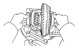
Install the differential case on the carrier, and install the 2 side shims so that there is no play in the bearing.
-
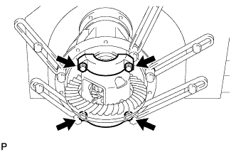
Install the 2 bearing caps with the 4 bolts.
- Torque:
- 85 N*m { 870 kgf*cm, 63 ft.*lbf }
-
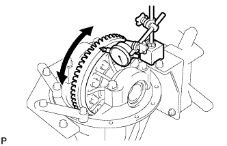
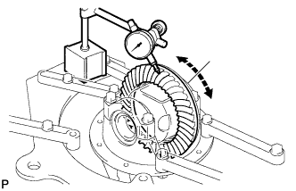
Using a dial indicator, measure the runout of the ring gear.
Maximum runout 0.07 mm (0.0028 in.) -
Remove the 2 bearing caps, 2 side shims and differential case.
-
-
INSTALL REAR DIFFERENTIAL DUST DEFLECTOR
-
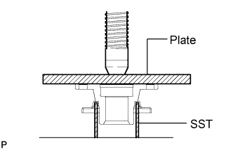
Using SST, a plate and a press, press in the dust deflector.
- SST
- 09636-20010
Note
Be careful not to damage the dust deflector.
-
-
INSTALL REAR DRIVE PINION FRONT TAPERED ROLLER BEARING
-
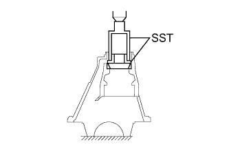
Using SST and a press, press the roller bearing (outer) to the carrier.
- SST
- 09316-60011 ( 09316-00011, 09316-00021 )
-
-
INSTALL REAR DRIVE PINION REAR TAPERED ROLLER BEARING
-
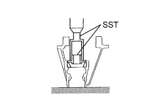
Using SST and a press, press the roller bearing (outer) into the carrier.
- SST
- 09316-60011 ( 09316-00041, 09316-00011 )
-
-
INSTALL REAR DRIVE PINION REAR TAPERED ROLLER BEARING
-
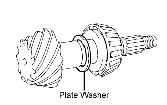
Install the plate washer on the drive pinion.
Tech Tips
First fit a washer with the same thickness as the removed washer, and then check the tooth contact pattern. Replace the washer with one of a different thickness if necessary.
-
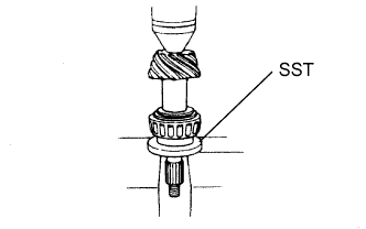
Using SST and a press, press the roller bearing (inner) onto the drive pinion.
- SST
- 09506-30012
-
-
ADJUST DIFFERENTIAL DRIVE PINION PRELOAD
-
Install a new bearing spacer to the drive pinion.
-
Install the rear drive pinion front tapered roller bearing.
-
Install the rear differential drive pinion oil slinger.
-
Apply MP grease to a new oil seal.
-
Using SST, install the companion flange on the drive pinion.
- SST
- 09950-30012 ( 09951-03010, 09953-03010, 09954-03010, 09955-03030, 09956-03040 )
Note
Before using SST (center bolt), apply hypoid gear oil to its threads and tip.
-
Using SST to hold the companion flange in place, torque the nut.
- SST
- 09330-00021 ( 09330-00030 )
-
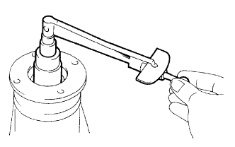
Using a torque wrench, measure the preload.
Standard preload (at start of torque) Bearing Preload New bearing 1.05 to 1.64 N*m (10.7 to 16.7 kgf*cm, 9.3 to 14.5 in.*lbf) Reused bearing 0.56 to 0.85 N*m (5.7 to 8.7 kgf*cm, 4.9 to 7.5 in.*lbf)
-
If the preload is greater than the maximum, replace the bearing spacer.
-
If the preload is less than the minimum, retighten the nut with 13 N*m (130 kgf*cm, 9 ft.*lbf) of torque at a time until the specified preload is reached.
- Torque:
- 678 N*m { 6,914 kgf*cm, 500 ft.*lbf }
-
If the maximum torque is exceeded while retightening the nut, replace the bearing spacer and repeat the preload adjusting procedure.
Tech Tips
Do not loosen the pinion nut to reduce the preload.
-
-
-
INSTALL DIFFERENTIAL CASE ASSEMBLY
-
Place the 2 bearing outer races on their respective bearings and 2 side shims.
Tech Tips
Make sure the right and left races are not interchanged.
-
Align matchmarks on the bearing cap and differential carrier, and install the 2 bearing caps.
Note
Make sure the right and left bearing caps are not interchanged.
-
Tighten both bearing caps with the 4 bolts.
- Torque:
- 85 N*m { 870 kgf*cm, 63 ft.*lbf }
-
-
INSPECT BACKLASH DIFFERENTIAL RING GEAR AND DIFFERENTIAL DRIVE PINION BACKLASH
- SST
- 09504-00011
- 09960-10010 ( 09962-01000, 09963-00700 )
-
Set the dial indicator perpendicular to the end of the ring gear face.
-
While holding the rear drive pinion companion flange, rotate the ring gear and measure the backlash.
Standard backlash 0.13 to 0.20 mm (0.0051 to 0.0078 in.)
-
ADJUST DIFFERENTIAL RING GEAR AND DIFFERENTIAL DRIVE PINION BACKLASH
-
Select a side shim so that the ring gear backlash is within the specification. Then, install it to the ring gear back side.
Tech Tips
-
If the case bearing is new, select a thinner side shim and install it.
-
If the case bearing is reused, install a side shim with the same thickness as the removed one.
Standard side shim thickness Thickness Thickness Thickness 2.51 mm (0.099 in.) 3.12 mm (0.123 in.) 3.73 mm (0.147 in.) 2.54 mm (0.100 in.) 3.15 mm (0.124 in.) 3.76 mm (0.148 in.) 2.57 mm (0.101 in.) 3.18 mm (0.125 in.) 3.78 mm (0.149 in.) 2.59 mm (0.102 in.) 3.20 mm (0.126 in.) 3.81 mm (0.150 in.) 2.62 mm (0.103 in.) 3.23 mm (0.127 in.) 3.84 mm (0.151 in.) 2.64 mm (0.104 in.) 3.25 mm (0.128 in.) 3.86 mm (0.152 in.) 2.67 mm (0.105 in.) 3.28 mm (0.129 in.) 3.89 mm (0.153 in.) 2.69 mm (0.106 in.) 3.30 mm (0.130 in.) 3.91 mm (0.154 in.) 2.72 mm (0.107 in.) 3.33 mm (0.131 in.) 3.94 mm (0.155 in.) 2.74 mm (0.108 in.) 3.35 mm (0.132 in.) 3.96 mm (0.156 in.) 2.77 mm (0.109 in.) 3.38 mm (0.133 in.) 3.99 mm (0.157 in.) 2.79 mm (0.110 in.) 3.40 mm (0.134 in.) 4.01 mm (0.158 in.) 2.82 mm (0.111 in.) 3.43 mm (0.135 in.) 4.04 mm (0.159 in.) 2.84 mm (0.112 in.) 3.45 mm (0.136 in.) 4.06 mm (0.160 in.) 2.87 mm (0.113 in.) 3.48 mm (0.137 in.) 4.09 mm (0.161 in.) 2.90 mm (0.114 in.) 3.51 mm (0.138 in.) 4.11 mm (0.162 in.) 2.92 mm (0.115 in.) 3.53 mm (0.139 in.) 4.14 mm (0.163 in.) 2.95 mm (0.116 in.) 3.56 mm (0.140 in.) 4.17 mm (0.164 in.) 2.97 mm (0.117 in.) 3.58 mm (0.141 in.) 4.19 mm (0.165 in.) 3.00 mm (0.118 in.) 3.61 mm (0.142 in.) 4.22 mm (0.166 in.) 3.02 mm (0.119 in.) 3.63 mm (0.143 in.) 4.24 mm (0.167 in.) 3.05 mm (0.120 in.) 3.66 mm (0.144 in.) 4.27 mm (0.168 in.) 3.07 mm (0.121 in.) 3.68 mm (0.145 in.) 4.29 mm (0.169 in.) 3.10 mm (0.122 in.) 3.71 mm (0.146 in.) -
-
-
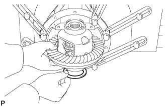
Make the differential case bearing and side shim snug by tapping on the ring gear with a plastic-faced hammer.
-
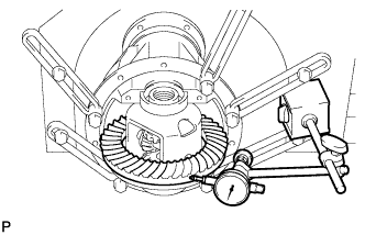
Set the dial indicator perpendicular to the end of the ring gear face.
-
While holding the rear drive pinion companion flange, rotate the ring gear and measure the backlash.
Standard backlash 0.13 to 0.20 mm (0.0051 to 0.0078 in.) -
If the backlash is not within the specification, select a side shim so that the ring gear backlash is within the specification. Then, install it to the ring gear back side.
-
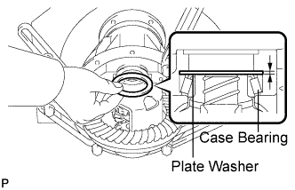
Select a thicker side shim so that the clearance between the case bearing outer race end on the ring gear teeth side and the carrier becomes 0 or around 0.
-
Make the differential case bearing and side shim snug by tapping on the ring gear with a plastic-faced hammer.
-
Select the dial indicator perpendicular to the end of the ring gear face.
-
While holding the rear drive pinion companion flange rear, rotate the ring gear and measure the backlash.
Standard backlash 0.13 to 0.20 mm (0.0051 to 0.0078 in.)
-
If the backlash is not within the specification, adjust the thickness of the right and left side shim by an equal amount so that the backlash is within the specification.
-
-
-
INSPECT TOTAL PRELOAD
-
Using a torque wrench, measure the preload with the teeth of the drive pinion and ring gear in contact.
Tech Tips
A bolt without a torque specification is shown in the service data Click here.
-
If necessary, disassemble and inspect the differential.
-
-
-
INSPECT TOOTH CONTACT BETWEEN RING GEAR AND DRIVE PINION
-
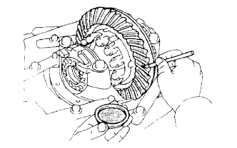
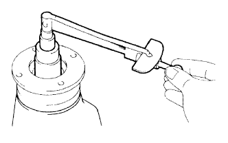
Coat 3 or 4 teeth at 3 different positions on the ring gear with red lead primer.
-
Hold the companion flange firmly in place and rotate the ring gear in both directions.
-
Inspect the tooth contact pattern.
-
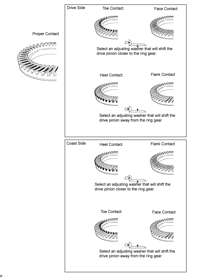
-
If the teeth are not contacting properly, use the following chart to select a proper washer.
Standard plate washer thickness Thickness mm (in.) Thickness mm (in.) 0.69 mm (0.0272 in.) 1.19 mm (0.0469 in.) 0.71 mm (0.0280 in.) 1.22 mm (0.0480 in.) 0.74 mm (0.0291 in.) 1.24 mm (0.0488 in.) 0.76 mm (0.0300 in.) 1.27 mm (0.0500 in.) 0.79 mm (0.0311 in.) 1.30 mm (0.0512 in.) 0.81 mm (0.0319 in.) 1.32 mm (0.0520 in.) 0.84 mm (0.0331 in.) 1.35 mm (0.0531 in.) 0.86 mm (0.0339 in.) 1.37 mm (0.0540 in.) 0.89 mm (0.0350 in.) 1.40 mm (0.0551 in.) 0.91 mm (0.0358 in.) 1.42 mm (0.0559 in.) 0.94 mm (0.0370 in.) 1.45 mm (0.0571 in.) 0.97 mm (0.0382 in.) 1.47 mm (0.0579 in.) 0.99 mm (0.0390 in.) 1.50 mm (0.0591 in.) 1.02 mm (0.0402 in.) 1.52 mm (0.0598 in.) 1.04 mm (0.0409 in.) 1.55 mm (0.0610 in.) 1.07 mm (0.0421 in.) 1.58 mm (0.0622 in.) 1.09 mm (0.0429 in.) 1.60 mm (0.0630 in.) 1.12 mm (0.0441 in.) 1.63 mm (0.0642 in.) 1.14 mm (0.0449 in.) 1.65 mm (0.0650 in.) 1.17 mm (0.0461 in.) -
-
-
-
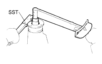
REMOVE REAR DRIVE PINION NUT
-
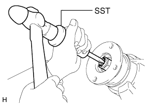
Using SST and a hammer, loosen the staked part of the nut.
- SST
- 09930-00010 ( 09931-00010, 09931-00020 )
-
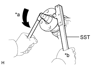
Text in Illustration *a Turn *b Hold Using SST to hold the companion flange in place, remove the nut.
- SST
- 09330-00021 ( 09330-00030 )
-
-
REMOVE REAR DRIVE PINION COMPANION FLANGE SUB-ASSEMBLY
-
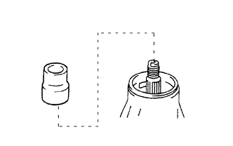
REMOVE REAR DIFFERENTIAL DRIVE PINION OIL SLINGER
-
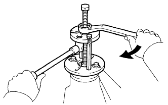
REMOVE REAR DRIVE PINION FRONT TAPERED ROLLER BEARING
-

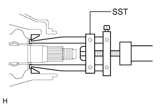
Using SST, remove the roller bearing (inner).
- SST
- 09556-22010
-
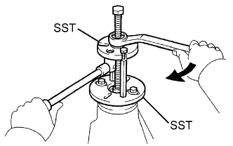
Using SST, tap out the roller bearing (outer).
- SST
- 09308-00010
-
-
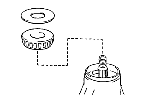
INSTALL REAR DIFFERENTIAL DRIVE PINION BEARING SPACER
-
Install a new bearing spacer to the drive pinion.
-
-
INSTALL DIFFERENTIAL OIL STORAGE RING
-
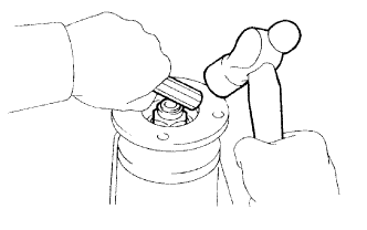
Using a brass bar and hammer, tap in a new oil storage ring.
Note
Be careful not to damage the oil storage ring.
-
-
INSTALL REAR DRIVE PINION FRONT TAPERED ROLLER BEARING
-
INSTALL REAR DIFFERENTIAL DRIVE PINION OIL SLINGER
-
INSTALL REAR DIFFERENTIAL CARRIER OIL SEAL
-
Apply MP grease to the lip of a new oil seal.
-
Using a brass bar and hammer, tap in a new oil seal until its surface is flush with the differential carrier end.
Note
Do not damage the oil seal.
-
-
INSTALL REAR DRIVE PINION COMPANION FLANGE SUB-ASSEMBLY
-
Using SST, install the companion flange on the drive pinion.
- SST
- 09950-30012 ( 09951-03010, 09953-03010, 09954-03010, 09955-03030, 09956-03040 )
Note
Before using SST (center bolt), apply hypoid gear oil to its threads and tip.
-
Using SST to hold the flange, torque the nut.
- SST
- 09330-00021 ( 09330-00030 )
- Torque:
- 370 N*m { 3,770 kgf*cm, 273 ft.*lbf, or less }
-
-
INSPECT DRIVE PINION PRELOAD
-
Using a torque wrench, measure the preload of the backlash between the drive pinion and ring gear.
Standard preload (at start of torque) Bearing Preload New bearing 1.20 to 2.00 N*m (12 to 20 kgf*cm, 11 to 18 in.*lbf) Reused bearing 0.70 to 1.50 N*m (7 to 15 kgf*cm, 6.0 to 13 in.*lbf)
-
If the preload is greater than the maximum, replace the bearing spacer.
-
If the preload is less than the minimum, retighten the nut with 13 N*m (130 kgf*cm, 9 ft.*lbf) of torque at a time until the specified preload is reached.
- Torque:
- 678 N*m { 6,914 kgf*cm, 500 ft.*lbf, or less }
-
If the maximum torque is exceeded while retightening the nut, replace the bearing spacer and repeat the preload adjusting procedure.
Tech Tips
Do not loosen the pinion nut to reduce the preload.
-
-
-
INSPECT TOTAL PRELOAD
-
Using a torque wrench, measure the preload.
Tech Tips
A bolt without a torque specification is shown in the service data Click here.
-
If necessary, disassemble and inspect the differential.
-
-
-
INSPECT DIFFERENTIAL RING GEAR BACKLASH
-
Using a dial indicator, measure the backlash of the ring gear.
Standard backlash 0.13 to 0.20 mm (0.0051 to 0.0078 in.)
-
If the backlash is not as specified, adjust the side bearing preload or repair as necessary.
Tech Tips
Perform the measurements at 3 or more positions around the circumference of the ring gear.
-
-
-
INSPECT RUNOUT OF REAR DRIVE PINION COMPANION FLANGE SUB-ASSEMBLY
-
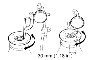
Using a dial indicator, measure the runout of the drive pinion companion flange vertically and laterally.
Maximum runout Runout Maximum Vertical runout 0.10 mm (0.0039 in.) Lateral runout 0.10 mm (0.0039 in.)
-
If the runout is greater than the maximum, replace the companion flange.
-
-
-
STAKE DRIVE PINION NUT
-
Using a chisel and hammer, stake the nut.
-