VEHICLE STABILITY CONTROL SYSTEM VSC OFF Indicator Light Remains ON
| DTC Code | DTC Name |
|---|---|
| VSC OFF Indicator Light Remains ON |
DESCRIPTION
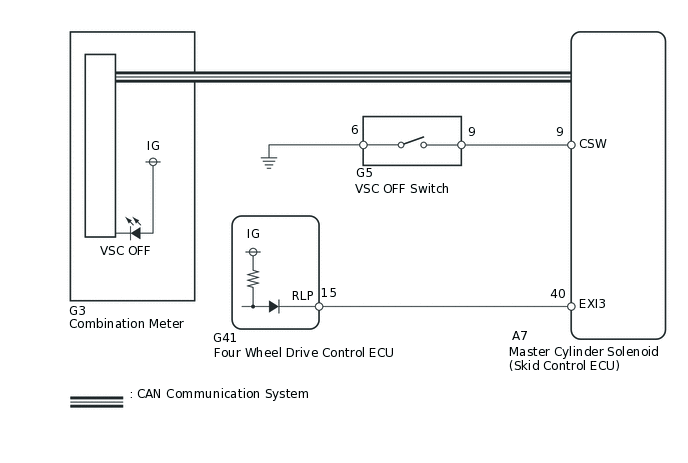
Operation of the VSC OFF switch changes the vehicle between normal mode, TRC OFF mode and VSC OFF mode. During normal mode, pressing the VSC OFF switch for a short amount of time changes vehicle to TRC OFF mode. When the vehicle is stopped, pressing the VSC OFF switch for 3 seconds or more changes the vehicle to VSC OFF mode.
When the transfer is in L4, VSC is prohibited and the VSC OFF indicator and TRC OFF indicator turn on.
WIRING DIAGRAM
CAUTION / NOTICE / HINT
When replacing the master cylinder solenoid, perform calibration (Click here).
As there may be malfunctions in the transfer system related to when the transfer operates in L4, check the transfer system first (Click here).
PROCEDURE
CHECK CAN COMMUNICATION LINE
Turn the engine switch off.
Connect the intelligent tester to the DLC3.
Turn the engine switch on (IG).
Turn the intelligent tester on.
Select CAN Bus Check from the System Selection Menu screen and follow the prompts on the screen to inspect the CAN bus.
OK
CAN Bus Check indicates no malfunctions in CAN communication.
Result
Result
OK
NG
CHECK HARNESS AND CONNECTOR (SKID CONTROL ECU CSW CIRCUIT)
Disconnect the A7 skid control ECU connector.
Measure the resistance according to the value(s) in the table below.
Standard Resistance
Tester Connection
Switch Condition
Specified Condition
A7-9 (CSW) - Body ground
VSC OFF switch not pushed in
10 kΩ or higher
VSC OFF switch pushed in
Below 1 Ω
Result
Result
OK
NG
NG CHECK HARNESS AND CONNECTOR (SKID CONTROL ECU - VSC OFF SWITCH)Click here
CHECK TERMINAL VOLTAGE (EXI3)
Disconnect the A7 skid control ECU connector.
-
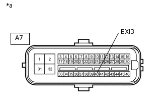
*a
Front view of wire harness connector
(to Skid Control ECU)
Measure the voltage according to the value(s) in the table below.
Standard Voltage
Tester Connection
Switch Condition
Specified Condition
A7-40 (EXI3) - Body ground
Engine switch on (IG)
11 to 14 V
Result
Result
OK
NG
NG CHECK HARNESS AND CONNECTOR (SKID CONTROL ECU EXI3 CIRCUIT)Click here
READ VALUE USING INTELLIGENT TESTER (TRC/VSC OFF MODE)
Turn the engine switch off.
Connect the intelligent tester to the DLC3.
Turn the engine switch on (IG).
Turn the intelligent tester on.
Enter the following menus: Chassis / ABS/VSC/TRC / Data List.
Chassis > ABS/VSC/TRC > Data List
Tester Display
Measurement Item
Range
Normal Condition
Diagnostic Note
TRC/VSC Off Mode
TRC/VSC off mode
Normal, TRC OFF or VSC OFF
Normal: Normal mode
TRC OFF: TRC OFF mode
VSC OFF: VSC OFF mode
-
Check that the mode display changes according to VSC OFF switch operation.
OK
Display changes according to switch operation.
Result
Result
OK
NG
CHECK HARNESS AND CONNECTOR (SKID CONTROL ECU EXI3 CIRCUIT)
Disconnect the A7 skid control ECU connector.
Disconnect the G41 four wheel drive control ECU connector.
Measure the resistance according to the value(s) in the table below.
Standard Resistance
Tester Connection
Condition
Specified Condition
A7-40 (EXI3) - Body ground
Always
10 kΩ or higher
Result
Result
OK
NG
NG REPAIR OR REPLACE HARNESS OR CONNECTOR
CHECK TERMINAL VOLTAGE (EXI3)
Disconnect the A7 skid control ECU connector.
-
*a
Front view of wire harness connector
(to Skid Control ECU)
Measure the voltage according to the value(s) in the table below.
Standard Voltage
Tester Connection
Switch Condition
Specified Condition
A7-40 (EXI3) - Body ground
Engine switch on (IG)
11 to 14 V
Result
Result
OK
NG
CHECK HARNESS AND CONNECTOR (SKID CONTROL ECU - VSC OFF SWITCH)
Disconnect the A7 skid control ECU connector.
Disconnect the G5 VSC OFF switch connector.
Measure the resistance according to the value(s) in the table below.
Standard Resistance
Tester Connection
Condition
Specified Condition
A7-9 (CSW) - G5-9
Always
Below 1 Ω
A7-9 (CSW) - Body ground
Always
10 kΩ or higher
G5-6 - Body ground
Always
Below 1 Ω
Result
Result
OK
NG
NG REPAIR OR REPLACE HARNESS OR CONNECTOR
INSPECT VSC OFF SWITCH
Remove the VSC OFF switch.
-
*a
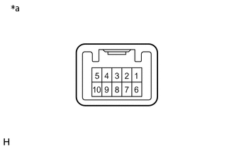
Component without harness connected
(VSC OFF Switch)
Measure the resistance according to the value(s) in the table below.
Standard Resistance
Tester Connection
Switch Condition
Specified Condition
9 - 6
Switch is not pushed
10 kΩ or higher
Switch is pushed
Below 1 Ω
Result
Result
OK
NG