PRE-CRASH SAFETY SYSTEM TERMINALS OF ECU
CHECK DRIVING SUPPORT ECU ASSEMBLY

Disconnect the G168 driving support ECU assembly connector.
Note:If a load of more than 10 kg (22 lb) is placed on the connector, it may break. Do not place more load than is necessary on the connector.
Measure the voltage and resistance according to the value(s) in the table below.
Terminal No. (Symbol)
Wiring Color
Terminal Description
Condition
Specified Condition
G168-28 (GND) - Body ground
BR - Body ground
Ground
Always
Below 1 Ω
G168-7 (B) - Body ground
B - Body ground*1
V - Body ground*2
Power source
Ignition switch ON
11 to 14 V*1
9.5 to 14 V*2
Ignition switch off
Below 1 V
*1: w/o Stop and Start System
*2: w/ Stop and Start System
Tip:If the result is not as specified, there may be a malfunction on the wire harness side.
Reconnect the G168 driving support ECU assembly connector.
Check for pulses according to the value(s) in the table below.
Terminal No. (Symbol)
Wiring Color
Terminal Description
Condition
Specified Condition
G168-3 (BZ) - Body ground
LG - Body ground
Skid control buzzer output
Ignition switch ON
Skid control buzzer operating
0 to 1.5 V
Ignition switch ON
Skid control buzzer not operating
11 to 14 V*1
9.5 to 14 V*2
G168-11 (CA2L) - G168-28 (GND)
LG - BR
CAN communication signal
Ignition switch ON
Pulse generation
(See waveform 1)
G168-9 (CA1N) - G168-28 (GND)
W - BR
CAN communication signal
Ignition switch ON
Pulse generation
(See waveform 2)
G168-10 (CA2H) - G168-28 (GND)
P - BR
CAN communication signal
Ignition switch ON
Pulse generation
(See waveform 3)
G168-8 (CA1P) - G168-28 (GND)
B - BR
CAN communication signal
Ignition switch ON
Pulse generation
(See waveform 4)
*1: w/o Stop and Start System
*2: w/ Stop and Start System
-
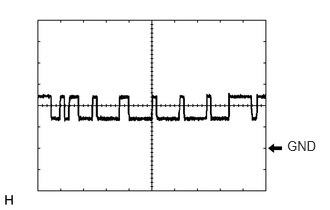
Waveform 1
CAN communication signal
Item
Content
Tester Connection
G168-11 (CA2L) - G168-28 (GND)
Tool Setting
1 V/DIV., 10 μsec./DIV.
Condition
Ignition switch ON
Tip:The waveform varies depending on the CAN communication signal.
-
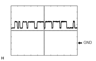
Waveform 2
CAN communication signal
Item
Content
Tester Connection
G168-9 (CA1N) - G168-28 (GND)
Tool Setting
1 V/DIV., 10 μsec./DIV.
Condition
Ignition switch ON
Tip:The waveform varies depending on the CAN communication signal.
-
Waveform 3
CAN communication signal
Item
Content
Tester Connection
G168-10 (CA2H) - G168-28 (GND)
Tool Setting
1 V/DIV., 10 μsec./DIV.
Condition
Ignition switch ON
Tip:The waveform varies depending on the CAN communication signal.
-
Waveform 4
CAN communication signal
Item
Content
Tester Connection
G168-8 (CA1P) - G168-28 (GND)
Tool Setting
1 V/DIV., 10 μsec./DIV.
Condition
Ignition switch ON
Tip:The waveform varies depending on the CAN communication signal.
CHECK MILLIMETER WAVE RADAR SENSOR ASSEMBLY
CHECK FORWARD RECOGNITION CAMERA
CHECK BRAKE ACTUATOR ASSEMBLY (SKID CONTROL ECU)