AIR CONDITIONING SYSTEM(for Manual Air Conditioning System), Diagnostic DTC:B1451
| DTC Code | DTC Name |
|---|---|
| B1451 | Compressor Solenoid Circuit |
DESCRIPTION
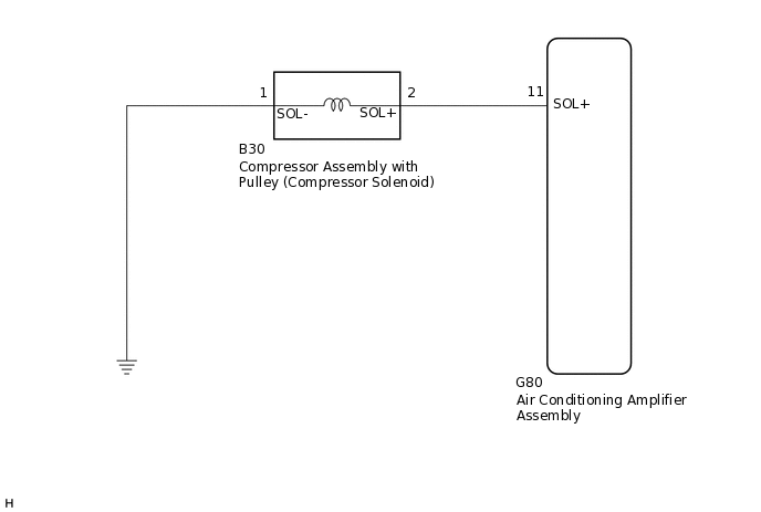
In this circuit, the compressor assembly with pulley (compressor solenoid) receives a refrigerant compression demand signal from the air conditioning amplifier assembly.
Based on this signal, the compressor assembly with pulley (compressor solenoid) changes the amount of compressor output.
DTC No. |
Detection Item |
DTC Detection Condition |
Trouble Area |
Memory |
|---|---|---|---|---|
B1451 |
Compressor Solenoid Circuit |
Open or short in compressor solenoid circuit |
|
- |
WIRING DIAGRAM
PROCEDURE
INSPECT COMPRESSOR ASSEMBLY WITH PULLEY (COMPRESSOR SOLENOID)
-
Remove the compressor assembly with pulley (compressor solenoid).
for 1AD-FTV, 2AD-FHV, 2AD-CCo, 2AD-DPF:
for 2AR-FE:
for 3ZR-FE, 3ZR-FAE:
Measure the resistance according to the value(s) in the table below.
Standard Resistance
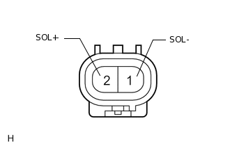
Tester Connection
Condition
Specified Condition
1 (SOL-) - 2 (SOL+)
20°C (68°F)
10.1 to 11.1 Ω
Result
Proceed to
OK
NG
NG REPLACE COMPRESSOR ASSEMBLY WITH PULLEY (COMPRESSOR SOLENOID)
for 1AD-FTV, 2AD-FHV, 2AD-CCo, 2AD-DPF:
for 2AR-FE:
for 3ZR-FE, 3ZR-FAE:
-
CHECK HARNESS AND CONNECTOR (COMPRESSOR ASSEMBLY WITH PULLEY [COMPRESSOR SOLENOID] - BODY GROUND)
-
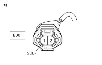
*a
Front view of wire harness connector
(to Compressor Assembly with Pulley)
Disconnect the compressor assembly with pulley (compressor solenoid) connector.
Measure the resistance according to the value(s) in the table below.
Standard Resistance
Tester Connection
Condition
Specified Condition
B30-1 (SOL-) - Body ground
Always
Below 1 Ω
Result
Proceed to
OK
NG
NG REPAIR OR REPLACE HARNESS OR CONNECTOR
-
CHECK HARNESS AND CONNECTOR (AIR CONDITIONING AMPLIFIER ASSEMBLY - COMPRESSOR ASSEMBLY WITH PULLEY [COMPRESSOR SOLENOID])
Disconnect the G80 air conditioning amplifier assembly connector.
Disconnect the B30 compressor with pulley assembly (compressor solenoid) connector.
Measure the resistance according to the value(s) in the table below.
Standard Resistance
Tester Connection
Condition
Specified Condition
G80-11 (SOL+) - B30-2 (SOL+)
Always
Below 1 Ω
G80-11 (SOL+) - Body ground
Always
10 kΩ or higher
Result
Result
Proceed to
OK (When troubleshooting according to Problem Symptoms Table)
A
OK (When troubleshooting according to the DTC)
B
NG
C
C REPAIR OR REPLACE HARNESS OR CONNECTOR