SHIFT LEVER ASSEMBLY DISASSEMBLY
PROCEDURE
REMOVE FLOOR SHIFT POSITION INDICATOR HOUSING SUB-ASSEMBLY
-
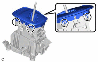
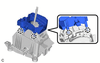
Disengage the 4 claws and remove the floor shift position indicator housing sub-assembly from the position indicator lower housing.
-
REMOVE INDICATOR LIGHT WIRE SUB-ASSEMBLY
-
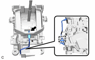
Disconnect the indicator light wire sub-assembly connector from the position indicator lower housing.
Disconnect the indicator light wire sub-assembly wire harness clamp from the shift lock control unit assembly.
-
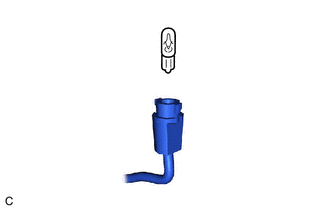
Remove the bulb from the indicator light wire sub-assembly.
-
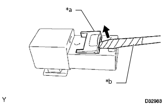
*a
Secondary Lock
*b
Protective Tape
Using a screwdriver, release the secondary lock.
Tip:Tape the screwdriver tip before use.
-
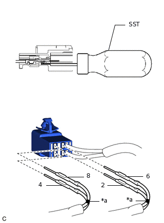
*a
Mark
Put marks on the wires for terminals 6 and 8.
Using SST, release the locking lugs of terminals 2, 4, 6 and 8, and pull the wires and terminals out of the indicator light wire sub-assembly connector.
09991-00510
-
REMOVE POSITION INDICATOR LOWER HOUSING
-
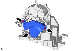
Disengage the 4 claws and remove the position indicator lower housing from the shift lock control unit assembly.
-
REMOVE SHIFT LEVER POSITION SENSOR
-
Remove the 3 screws and shift lever position sensor.
-
REMOVE POSITION INDICATOR SLIDE COVER
Remove the position indicator slide cover from the shift lock control unit assembly.
-
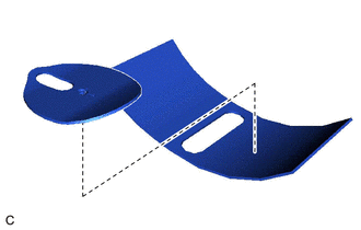
Remove the No. 2 position indicator slide cover from the position indicator slide cover.
REMOVE SHIFT LOCK RELEASE BUTTON
-
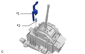
*1
Shift Lock Release Button
*2
Compression Spring
Remove the shift lock release button and compression spring from the shift lock control unit assembly.
-