AIR CONDITIONING SYSTEM(for Automatic Air Conditioning System), Diagnostic DTC:B1451/51
| DTC Code | DTC Name |
|---|---|
| B1451/51 | Compressor Solenoid Circuit |
DESCRIPTION
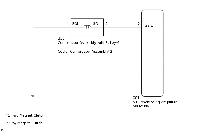
In this circuit, the compressor assembly with pulley*1 or cooler compressor assembly*2 receives a refrigerant compression demand signal from the air conditioning amplifier assembly.
Based on this signal, the compressor assembly with pulley*1 or cooler compressor assembly*2 changes the amount of compressor output.
*1: w/o Magnet Clutch
*2: w/ Magnet Clutch
DTC No. |
Detection Item |
DTC Detection Condition |
Trouble Area |
Memory |
Note |
|---|---|---|---|---|---|
B1451/51 |
Compressor Solenoid Circuit |
Open or short in compressor solenoid circuit |
|
- |
- |
The air conditioning amplifier assembly stores the DTC of the respective malfunction if it has occurred for the period of time indicated in the brackets.
WIRING DIAGRAM
CAUTION / NOTICE / HINT
When the battery is disconnected or the air conditioning amplifier assembly is replaced, be sure to perform servo motor initialization.
PROCEDURE
READ VALUE USING GTS
Connect the GTS to the DLC3.
Turn the ignition switch to ON.
Turn the GTS on.
Enter the following menus: Body Electrical / Air Conditioner / Data List.
Check the value(s) by referring to the table below.
Body Electrical > Air Conditioner > Data List
Tester Display
Measurement Item
Range
Normal Condition
Diagnostic Note
Regulator Control Current
Solenoid valve control current
Min.: 0 A
Max.: 0.997 A
Value changes between 0 A and 0.997 A in accordance with solenoid valve operation
-
Body Electrical > Air Conditioner > Data List
Tester Display
Regulator Control Current
OK
The display is as specified in the normal condition column.
Result
Result
Proceed to
OK (When troubleshooting according to Problem Symptoms Table)
A
OK (When troubleshooting according to the DTC)
B
NG (w/o Magnet Clutch)
C
NG (w/ Magnet Clutch)
D
D INSPECT COOLER COMPRESSOR ASSEMBLYClick here
INSPECT COMPRESSOR ASSEMBLY WITH PULLEY
Remove the compressor assembly with pulley.
for 2WW:Click hereClick here
for 3ZR-FE, 3ZR-FAE:Click hereClick here
for 2AD-FHV, 2AD-FTV:Click here
Inspect the compressor assembly with pulley.
for 2WW:Click here
for 3ZR-FE, 3ZR-FAE:Click here
for 2AD-FHV, 2AD-FTV:Click here
Result
Proceed to
OK
NG
NG REPLACE COMPRESSOR ASSEMBLY WITH PULLEY
for 2WW:Click hereClick here
for 3ZR-FE, 3ZR-FAE:Click hereClick here
for 2AD-FHV, 2AD-FTV:Click here
CHECK HARNESS AND CONNECTOR (COMPRESSOR ASSEMBLY WITH PULLEY - BODY GROUND)
-
*a
Front view of wire harness connector
(to Compressor Assembly with Pulley)
Disconnect the compressor assembly with pulley connector.
Measure the resistance according to the value(s) in the table below.
Standard Resistance
Tester Connection
Condition
Specified Condition
B30-1 (SOL-) - Body ground
Always
Below 1 Ω
Result
Proceed to
OK
NG
NG REPAIR OR REPLACE HARNESS OR CONNECTOR
-
CHECK HARNESS AND CONNECTOR (COMPRESSOR ASSEMBLY WITH PULLEY - AIR CONDITIONING AMPLIFIER ASSEMBLY)
Disconnect the G81 air conditioning amplifier assembly connector.
Disconnect the B30 compressor assembly with pulley connector.
Measure the resistance according to the value(s) in the table below.
Standard Resistance
Tester Connection
Condition
Specified Condition
G81-2 (SOL+) - B30-2 (SOL+)
Always
Below 1 Ω
G81-2 (SOL+) - Body ground
Always
10 kΩ or higher
Result
Result
Proceed to
OK (When troubleshooting according to Problem Symptoms Table)
A
OK (When troubleshooting according to the DTC)
B
NG
C
C REPAIR OR REPLACE HARNESS OR CONNECTOR
INSPECT COOLER COMPRESSOR ASSEMBLY
Remove the cooler compressor assembly.
Inspect the cooler compressor assembly.
Result
Proceed to
OK
NG
CHECK HARNESS AND CONNECTOR (COOLER COMPRESSOR ASSEMBLY - BODY GROUND)
-
*a
Front view of wire harness connector
(to Cooler Compressor Assembly)
Disconnect the cooler compressor assembly connector.
Measure the resistance according to the value(s) in the table below.
Standard Resistance
Tester Connection
Condition
Specified Condition
B30-1 (SOL-) - Body ground
Always
Below 1 Ω
Result
Proceed to
OK
NG
NG REPAIR OR REPLACE HARNESS OR CONNECTOR
-
CHECK HARNESS AND CONNECTOR (COOLER COMPRESSOR ASSEMBLY - AIR CONDITIONING AMPLIFIER ASSEMBLY)
Disconnect the G81 air conditioning amplifier assembly connector.
Disconnect the B30 cooler compressor assembly connector.
Measure the resistance according to the value(s) in the table below.
Standard Resistance
Tester Connection
Condition
Specified Condition
G81-2 (SOL+) - B30-2 (SOL+)
Always
Below 1 Ω
G81-2 (SOL+) - Body ground
Always
10 kΩ or higher
Result
Result
Proceed to
OK (When troubleshooting according to Problem Symptoms Table)
A
OK (When troubleshooting according to the DTC)
B
NG
C
C REPAIR OR REPLACE HARNESS OR CONNECTOR