CYLINDER HEAD GASKET(w/ Glow Plug Controller) INSTALLATION
PROCEDURE
INSTALL CYLINDER HEAD GASKET
-
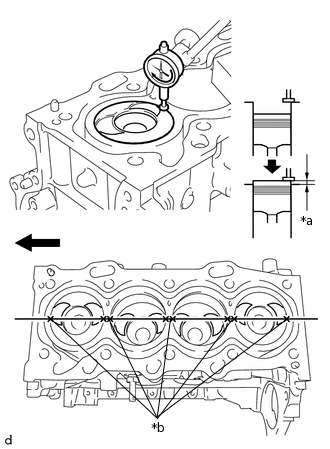
*a
Protrusion
*b
Measurement Points

Front of Engine
Inspect the protrusion height of the piston heads.
Place a dial indicator on the cylinder block sub-assembly as shown in the illustration.
Note:Make sure that the dial indicator is at a right angle to the cylinder block sub-assembly top surface.
Measure the protrusion height of the piston head of each cylinder at 2 points as shown in the illustration.
-
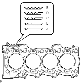
Select a new cylinder head gasket.
Select the highest protrusion height among the 8 measurements recorded. It will be used to select a new cylinder head gasket.
Piston Protrusion
Piston Protrusion
mm (in.)
Number of Gasket Cutouts
Gasket Size
0.525 to 0.575
(0.0207 to 0.0226)
1
(A)
0.576 to 0.625
(0.0227 to 0.0246)
2
(B)
0.626 to 0.675
(0.02465 to 0.02657)
3
(C)
0.676 to 0.725
(0.0266 to 0.0285)
4
(D)
0.726 to 0.775
(0.0286 to 0.0305)
5
(E)
Install the cylinder head gasket.
Apply seal packing (diameter 3.5 to 4.5 mm (0.138 to 0.177 in.)) to the cylinder block sub-assembly as shown in the illustration.
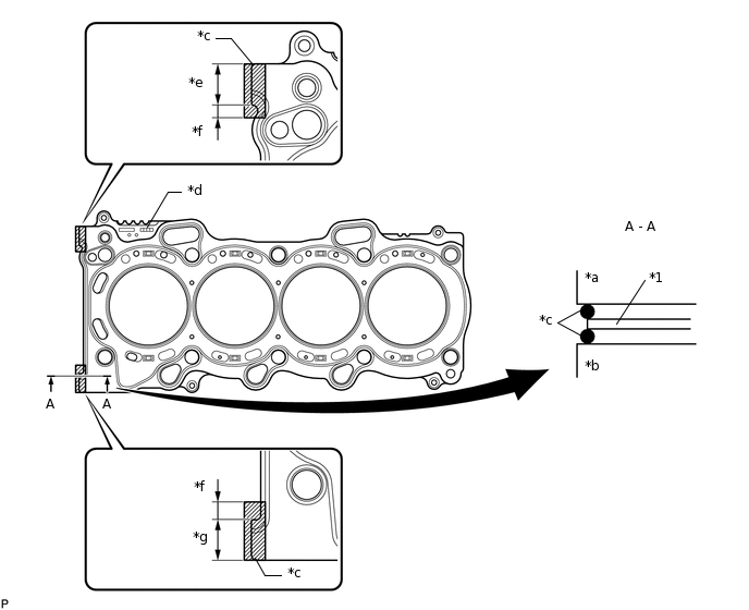
*1
Cylinder Head Gasket
-
-
*a
Cylinder Head Side
*b
Cylinder Block Side
*c
Seal Packing
*d
Lot No.
*e
18.0 mm (0.709 in.)
*f
1.0 to 6.0 mm (0.0394 to 0.236 in.)
*g
18.5 mm (0.728 in.)
-
-
Seal Packing
Toyota Genuine Seal Packing Black, Three Bond 1207B or equivalent
Note:Remove any oil from the contact surface.
Place a new cylinder head gasket on the cylinder block sub-assembly with the Lot No. stamp facing upward.
Apply seal packing (Diameter 3.5 to 4.5 mm (0.138 to 0.177 in.)) to the top surface of the cylinder head sub-assembly again as shown in the illustration.
Seal Packing
Toyota Genuine Seal Packing Black, Three Bond 1207B or equivalent
Note:Remove any oil from the contact surface.
Install the cylinder head sub-assembly within 3 minutes, and tighten the bolts within 15 minutes of applying the seal packing.
Do not start the engine for at least 2 hours after installing the cylinder head gasket.
-
INSTALL CYLINDER HEAD SUB-ASSEMBLY
CONNECT WATER INLET HOSE RH
-
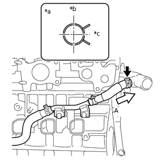
*a
View (A)
*b
Upper of Engine
*c
Rear of Engine
Connect the water inlet hose RH to the water outlet sub-assembly and slide the hose clip to secure it.
Note:Perform the installation with the hose clip at the correct angle.
-
INSTALL NO. 1 VALVE ROCKER ARM SUB-ASSEMBLY
INSTALL CAMSHAFT
INSTALL CHAIN SUB-ASSEMBLY
INSTALL NO. 1 CHAIN VIBRATION DAMPER
INSTALL CHAIN TENSIONER SLIPPER
INSTALL NO. 1 CHAIN TENSIONER ASSEMBLY
INSTALL TIMING CHAIN COVER OIL SEAL
INSTALL TIMING CHAIN COVER SUB-ASSEMBLY
CONNECT WATER INLET HOSE LH
INSTALL CRANKSHAFT DAMPER SUB-ASSEMBLY
INSTALL CAMSHAFT POSITION SENSOR
INSTALL NO. 2 TIMING CHAIN COVER
INSTALL ENGINE MOUNTING BRACKET RH
CHECK VALVE CLEARANCE
ADJUST VALVE CLEARANCE
INSTALL CYLINDER HEAD COVER SUB-ASSEMBLY
INSTALL V-RIBBED BELT TENSIONER ASSEMBLY
INSTALL VACUUM PUMP ASSEMBLY
INSTALL WATER BY-PASS PIPE SUB-ASSEMBLY
INSTALL NO. 2 OIL COOLER HOSE
INSTALL INJECTION NOZZLE SEAT
INSTALL INJECTOR ASSEMBLY
INSTALL NOZZLE HOLDER CLAMP SEAT
INSTALL NO. 1 NOZZLE HOLDER CLAMP
INSTALL COMMON RAIL ASSEMBLY
INSTALL GLOW PLUG ASSEMBLY
INSTALL NO. 1 GLOW PLUG CONNECTOR
INSTALL SUPPLY PUMP ASSEMBLY
INSTALL FUEL PUMP PROTECTOR
INSTALL NO. 2 NOZZLE LEAKAGE PIPE
CONNECT NO. 2 FUEL HOSE
CONNECT NO. 1 FUEL HOSE
INSTALL NO. 4 INJECTION PIPE SUB-ASSEMBLY
INSTALL FUEL INLET PIPE SUB-ASSEMBLY
INSTALL NO. 3 INJECTION PIPE SUB-ASSEMBLY
INSTALL NO. 2 INJECTION PIPE SUB-ASSEMBLY
INSTALL NO. 1 INJECTION PIPE SUB-ASSEMBLY
INSTALL NOZZLE LEAKAGE PIPE ASSEMBLY
INSTALL INTAKE AIR CONNECTOR WITH DIESEL THROTTLE BODY
INSTALL ENGINE OIL LEVEL DIPSTICK GUIDE
INSTALL ENGINE OIL LEVEL DIPSTICK
INSTALL EGR VALVE (ELECTRIC EGR CONTROL VALVE ASSEMBLY)
INSTALL HARNESS BRACKET (for LHD)
INSTALL HARNESS BRACKET (for RHD)
INSTALL NO. 1 EGR COOLER BRACKET
INSTALL EGR WITH COOLER PIPE ASSEMBLY
INSTALL GENERATOR BRACKET
INSTALL GENERATOR ASSEMBLY
INSTALL ENGINE COVER BRACKET
REMOVE ENGINE FROM ENGINE STAND