MULTI-MODE MANUAL TRANSAXLE SYSTEM, Diagnostic DTC:P0920
| DTC Code | DTC Name |
|---|---|
| P0920 | Gear Shift Forward Actuator Circuit |
DESCRIPTION
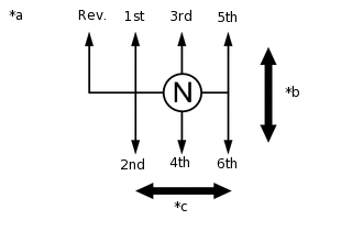
*a |
Shift and Select Actuator Operation |
*b |
Shift Direction |
*c |
Select Direction |
The shift and select actuator is operated by the TCM and changes the transaxle gear by the shift and select lever shaft movement. An electric motor (shift motor) moves the shift and select lever shaft in the shift direction, and the shift stroke sensor, which is mounted on the shift and select actuator assembly, detects the shift position. The TCM monitors the electrical current and shift motor output terminal voltage, and detects malfunctions in the shift motor circuit.
DTC No. |
Detection Item |
DTC Detection Condition |
Trouble Area |
MIL |
Warning Indicate |
Memory |
|---|---|---|---|---|---|---|
P0920 |
Gear Shift Forward Actuator Circuit |
The TCM detects the following conditions: (1-trip detection logic)
The TCM detects the following conditions: (1-trip detection logic)
The TCM detects the following conditions: (1-trip detection logic)
|
|
Does not come on |
Comes on |
DTC stored |
*1: A short between the shift motor circuit and the body ground is suspected.
*2: A short between the shift motor circuit and the +B circuit is suspected.
*3: An open in the shift motor circuit is suspected. When the motor current does not flow to the ECU terminals despite the ECU ordering the shift motor to operate, the ECU stores this DTC.
*4: An open in the shift motor circuit is suspected. When the difference is more than the threshold despite the ECU not ordering the shift motor to operate, the ECU stores this DTC.
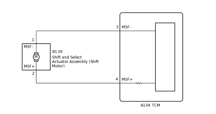
WIRING DIAGRAM
CAUTION / NOTICE / HINT
When installing parts related to the multi-mode manual transaxle system, perform the initialization and learning and synchronization position calibration procedures. In addition, the required operations differ according to the parts to be installed. Proceed with the operation in the order shown in the table below.
Part Installed |
Operation Order |
See Procedure |
|---|---|---|
|
1. Initialization and learning of multi-mode manual transaxle system |
|
2. Synchronization position calibration |
||
|
1. Initialization and learning of multi-mode manual transaxle system |
If the sensor or actuator is installed without the initialization and learning procedures, it may cause driving performance degradation or system component breakage.
PROCEDURE
INSPECT TCM (MSF TERMINAL VOLTAGE)
Result
Proceed to
OK
NG
CHECK TERMINAL CONDITION (TCM)
Result
Proceed to
OK
NG
NG CONNECT CORRECTLY
CHECK SHIFT MOTOR CIRCUIT
Result
Proceed to
OK
NG
NG CHECK TERMINAL CONDITION (SHIFT MOTOR)Click here
REPLACE TCM
Replace the TCM.
Result
Proceed to
NEXT
CHECK TERMINAL CONDITION (SHIFT MOTOR)
Result
Proceed to
OK
NG
NG CONNECT CORRECTLY
CHECK HARNESS AND CONNECTOR (TCM - SHIFT MOTOR)
Result
Proceed to
OK
NG
NG REPAIR OR REPLACE HARNESS OR CONNECTOR
INSPECT SHIFT AND SELECT ACTUATOR ASSEMBLY (SHIFT MOTOR)
Result
Proceed to
OK
NG
REPLACE SHIFT AND SELECT ACTUATOR ASSEMBLY
Replace the shift and select actuator assembly.
Result
Proceed to
NEXT