AUTOMATIC TRANSAXLE SYSTEM
-
CONSTRUCTION
-
The 6-speed configuration has been achieved by using 2 planetary gear units, creating a 6-speed automatic transaxle.
-
A Ravigneaux type planetary gear unit is used as the rear gear unit. The gear unit consists of pairs of sun gears (front and rear) and planetary pinion gears (long and short) with different diameters within a single planetary gear.
-
A centrifugal fluid pressure canceling mechanism is used in the C1 and C2 clutches that are applied when shifting between 1st to 6th gears.
-
The shapes of the grooves in the clutches and brake linings have been optimized in order to reduce drag.
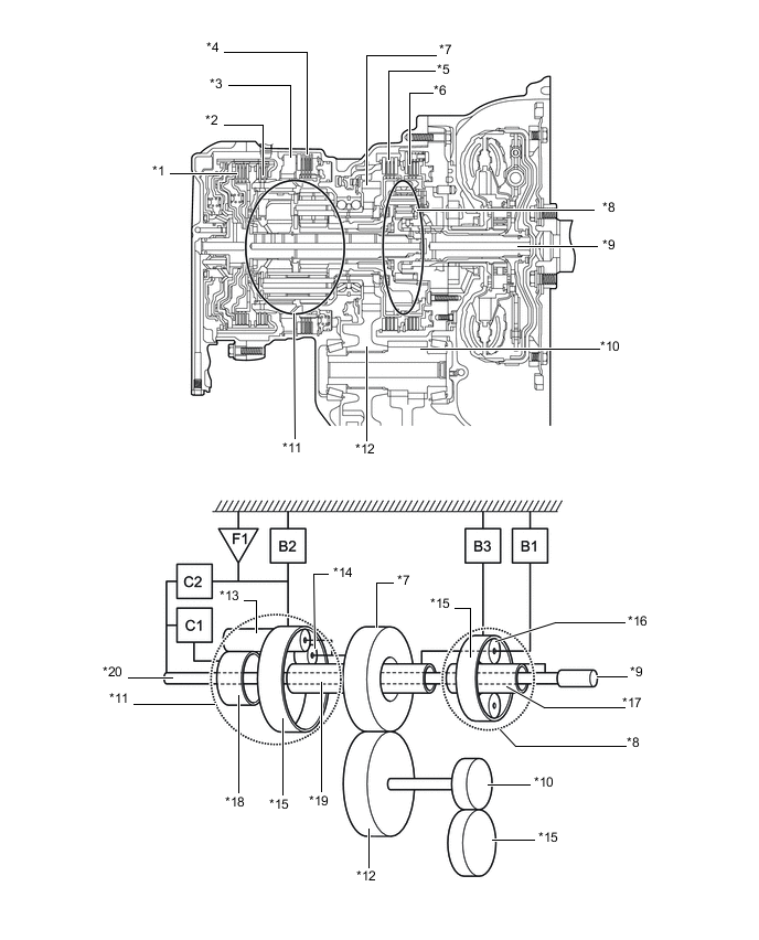
*1 No. 1 Clutch (C1) *2 No. 2 Clutch (C2) *3 No. 1 One-way Clutch (F1) *4 No. 2 Brake (B2) *5 No. 3 Brake (B3) *6 No. 1 Brake (B1) *7 Counter Drive Gear *8 Underdrive Planetary Gear Unit *9 Input Shaft *10 Differential Drive Pinion *11 Ravigneaux Planetary Gear Unit *12 Counter Driven Gear *13 Long Pinion Gear *14 Short Pinion Gear *15 Ring Gear *16 Pinion Gear *17 Sun Gear *18 Rear Sun Gear *19 Front Sun Gear *20 Front Sun Gear -
The functions of the clutches and brakes are as follows:
Component Function C1 No. 1 Clutch Connects the intermediate shaft and Ravigneaux planetary rear sun gear. C2 No. 2 Clutch Connects the intermediate shaft and Ravigneaux planetary ring gear. B1 No. 1 Brake Prevents the Ravigneaux planetary front sun gear and underdrive planetary carrier from turning either clockwise or counterclockwise. B2 No. 2 Brake Prevents the Ravigneaux planetary ring gear from turning either clockwise or counterclockwise. B3 No. 3 Brake Prevents the underdrive planetary ring gear from turning either clockwise or counterclockwise. F1 No. 1 One-way Clutch Prevents the Ravigneaux planetary ring gear from turning counterclockwise. Planetary Gears These gears change the route through which driving force is transmitted, in accordance with the operation of each clutch and brake, in order to increase or reduce the input and output speeds.
-
-
OPERATION
-
Transmission Power Flow
Shift Lever Position Gear Shift Solenoid Valve Clutch Brake One-way Clutch SL SL1 SL2 SL3 SL4 SLU C1 C2 B1 B2 B3 F1 P Park - ○ - - - - - - - - - - R Reverse ● - - - ○ - - - - ○ ○ - N Neutral - ○ - - - - - - - - - - D, S6 1st - ○ - - - - ○ - - - - ○ 2nd ○ ○ - ○ - ▲ ○ - ○ - - - 3rd ○ ○ - - ○ ▲ ○ - - - ○ - 4th ○ ○ ○ - - ▲ ○ ○ - - - - 5th ○ - ○ - ○ ▲ - ○ - - ○ - 6th ○ - ○ ○ - ▲ - ○ ○ - - - S5 1st - ○ - - - - ○ - - - - ○ 2nd ○ ○ - ○ - ▲ ○ - ○ - - - 3rd ○ ○ - - ○ ▲ ○ - - - ○ - 4th ○ ○ ○ - - ▲ ○ ○ - - - - 5th ○ - ○ - ○ ▲ - ○ - - ○ - S4 1st - ○ - - - - ○ - - - - ○ 2nd ○ ○ - ○ - ▲ ○ - ○ - - - 3rd ○ ○ - - ○ ▲ ○ - - - ○ - 4th ○ ○ ○ - - ▲ ○ ○ - - - - S3 1st - ○ - - - - ○ - - - - ○ 2nd - ○ - ○ - - ○ - ○ - - - 3rd - ○ - - ○ - ○ - - - ○ - S2 1st - ○ - - - - ○ - - - - ○ 2nd - ○ - ○ - - ○ - ○ - - - S1 1st - ○ - - - ○ ○ - - ○ - ○ ○: Operates
-: Does not operate
●: ON while engaging, OFF after engaged
▲: In accordance with flex lock-up
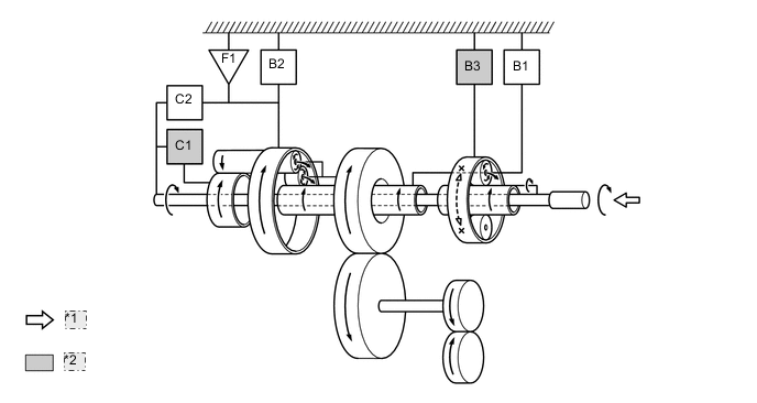
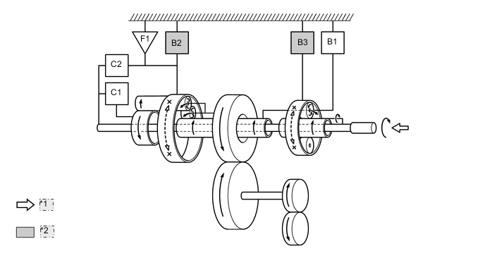
Figure 1. 1st Gear (S1 Range)
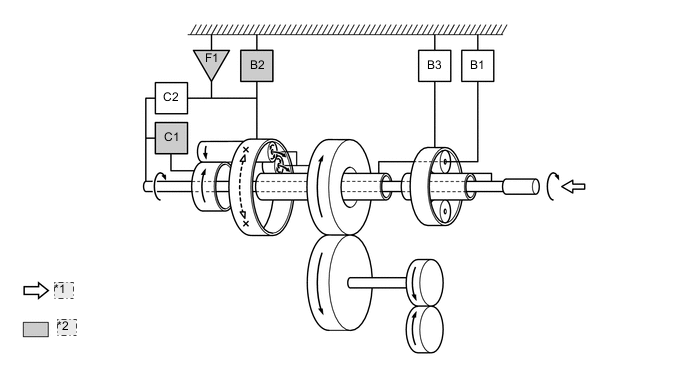
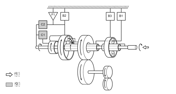
*1 Input *2 Operates Figure 2. 1st Gear (Shift lever in D or S*)
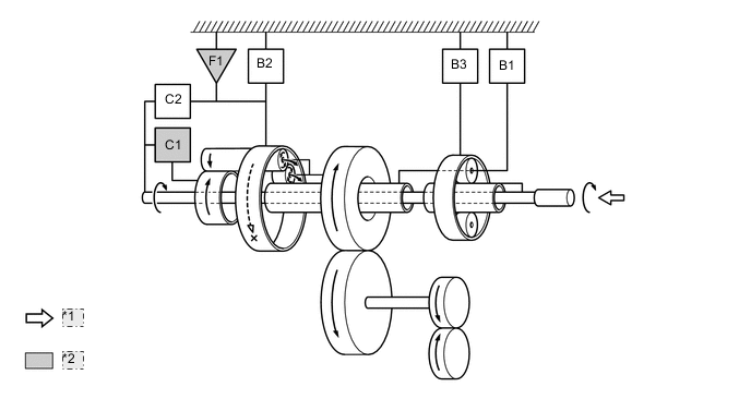
*1 Input *2 Operates *: Dose not include S1 range
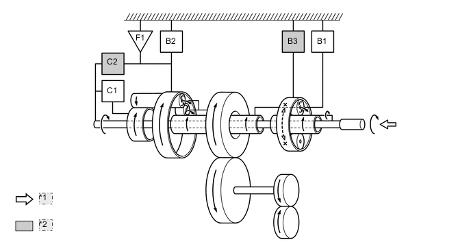
Figure 3. 2nd Gear (Shift lever in D or S)
*1 Input *2 Operates Figure 4. 3rd Gear (Shift lever in D or S)
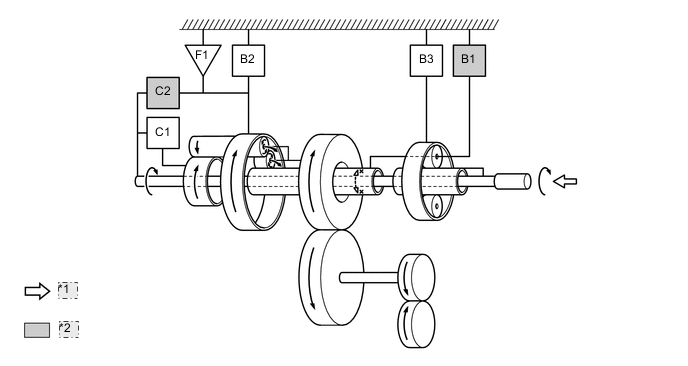
*1 Input *2 Operates Figure 5. 4th Gear (Shift lever in D or S)
*1 Input *2 Operates Figure 6. 5th Gear (Shift lever in D or S)
*1 Input *2 Operates Figure 7. 6th Gear (Shift lever in D or S)
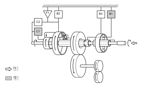
*1 Input *2 Operates Figure 8. Reverse (Shift lever in R)
*1 Input *2 Operates
-