СИСТЕМА SFI
-
CONSTRUCTION
-
Magnetic Resistance Element (MRE) type intake and exhaust cam position sensors are used.
-
To detect the camshaft position, timing rotors that are secured to the camshaft in front of the VVT controllers are used to generate 3 high output and 3 low output signals for every 2 revolutions of the crankshaft.
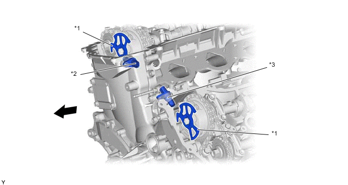
*1 Timing Rotor *2 Cam Position Sensor (Bank 1) *3 Cam Position Sensor (Bank 2) - - 
Engine Front - - Figure 1. Sensor Output Waveforms
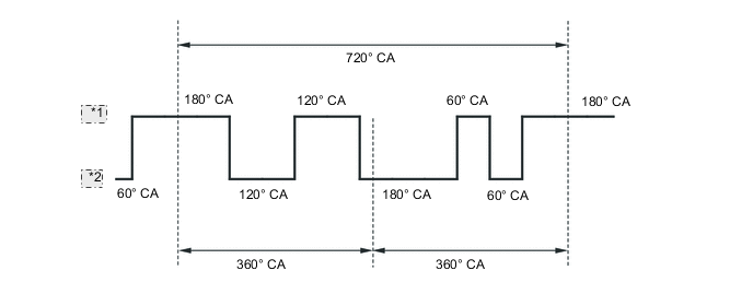
*1 High *2 Low -
The MRE type cam position sensor consists of an MRE, a magnet and a sensor. The direction of the magnetic field changes due to the different shapes (protruded and non-protruded portions) of the timing rotor, which passes by the sensor. As a result, the resistance of the MRE changes, and the output voltage to the ECM changes to high or low. The ECM detects the cam position based on this output voltage.
-
The differences between the MRE type sensor and the pick-up coil type sensor are as follows:
-
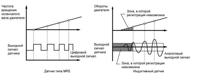
The MRE type sensor outputs a constant level of high and low digital signals regardless of the engine speed. Therefore, the MRE type sensor can detect the positions of the crankshaft and camshaft at an early stage of cranking.
-
The pick-up coil type sensor outputs analog signals with levels that change with the engine speed.
Figure 2. MRE Type and Pick-up Coil Type Output Waveform Image Comparison
-
-