STEERING COLUMN SYSTEM
-
CONSTRUCTION
-
Manual Tilt and Telescopic Mechanism
-
The tilt and telescopic mechanism consists mainly of the tilt and telescopic lever, column tube, column tube attachment, column tube bracket, breakaway bracket, and tilt and telescopic steering stopper.
-
When the tilt and telescopic mechanism is in its locked state, the tilt and telescopic lever at the locked position causes the tilt and telescopic steering stopper to tighten the column tube attachment and column tube bracket. This secures the column tube, so movement in the tilt direction and in the telescopic direction is locked.
-
When the tilt and telescopic mechanism is in its unlocked state, the tilt and telescopic lever at the unlocked position causes the tilt and telescopic steering stopper to loosen the column tube attachment and column tube bracket. This frees the column tube to move in the tilt direction and in the telescopic direction, enabling adjustment.
-
The tilt adjustment range is 30 mm (1.18 in.).
-
The telescopic adjustment range is 40 mm (1.57 in.).
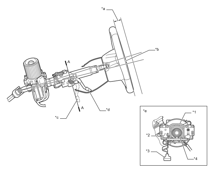
Text in Illustration (RHD Models:) *1 Column Tube Attachment *2 Tilt and Telescopic Steering Stopper *3 Tilt and Telescopic Lever *4 Column Tube *a 40 mm (1.57 in.) *b 30 mm (1.18 in.) *c Unlocked Position *d Locked Position *e A-A Cross Section - - 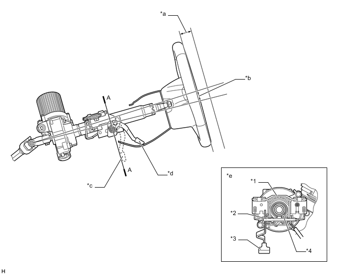
Text in Illustration (LHD Models (Except Models for Korea):) *1 Column Tube Attachment *2 Tilt and Telescopic Steering Stopper *3 Tilt and Telescopic Lever *4 Column Tube *a 40 mm (1.57 in.) *b 30 mm (1.18 in.) *c Unlocked Position *d Locked Position *e A-A Cross Section - - 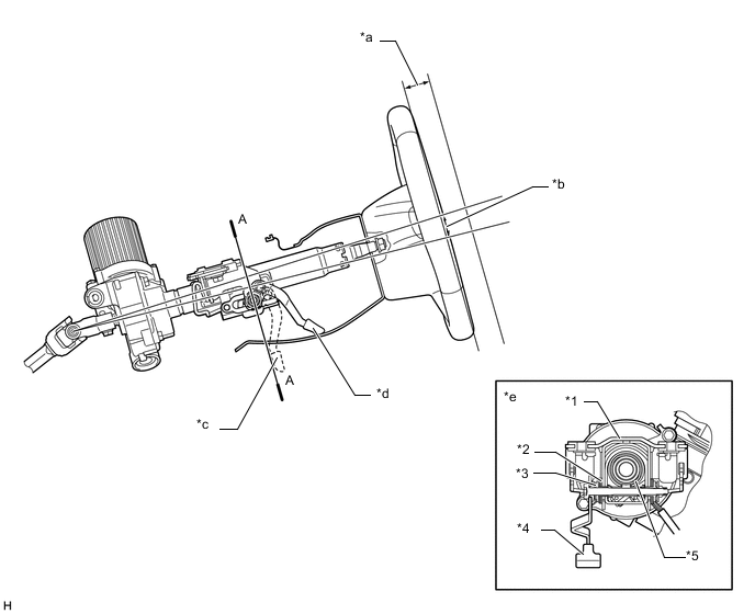
Text in Illustration (LHD Models (Models for Korea):) *1 Column Tube Attachment *2 Positive Lock Plate *3 Tilt and Telescopic Steering Stopper *4 Tilt and Telescopic Lever *5 Column Tube - - *a 40 mm (1.57 in.) *b 30 mm (1.18 in.) *c Unlocked Position *d Locked Position *e A-A Cross Section - -
-
-
Energy Absorbing Mechanism
-
The energy absorbing mechanism in the steering column assembly consists of main shaft column tube and steering intermediate shaft.
-
The steering column assembly is mounted on the instrument panel reinforcement assembly. The steering column assembly and the rack and pinion power steering gear assembly are connected with a contractile No.2 steering intermediate shaft assembly.
-
When the rack and pinion power steering gear assembly moves during a collision, the No.2 steering intermediate shaft assembly contracts, thus helping reduce the possibility of the steering column assembly and the steering wheel protruding into the cabin.
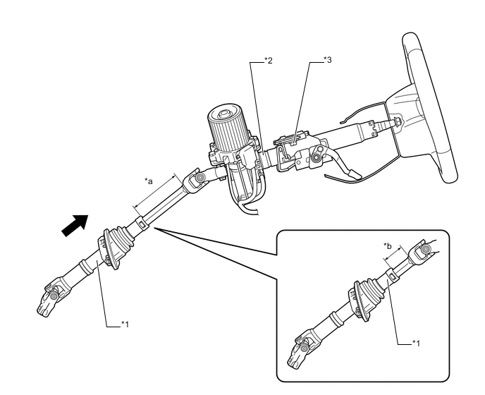
Text in Illustration (RHD Models:) *1 No.2 Steering Intermediate Shaft Assembly *2 Steering Column Assembly *3 Breakaway Bracket - - *a Before Primary Collision *b After Primary Collision 
Contract - - 
Text in Illustration (LHD Models (Except Models for Korea):) *1 No.2 Steering Intermediate Shaft Assembly *2 Steering Column Assembly *3 Breakaway Bracket - - *a Before Primary Collision *b After Primary Collision Contract - - 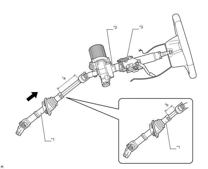
Text in Illustration (LHD Models (Models for Korea):) *1 No.2 Steering Intermediate Shaft Assembly *2 Steering Column Assembly *3 Breakaway Bracket - - *a Before Primary Collision *b After Primary Collision Contract - -
-
-
Steering Wheel Assembly
-
The steering shake damper is mounted to the steering wheel via a piece of rubber. This rubber mounting of the damper makes it possible for the vibration of the damper to cancel the vibration of the steering wheel, thus improving steering feel.
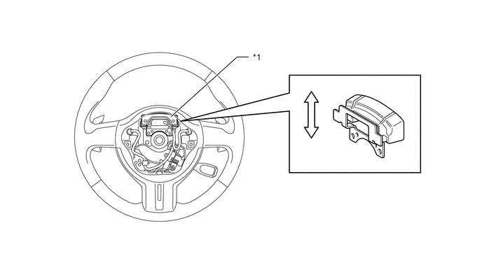
Text in Illustration *1 Steering Shake Damper - - 
Vibration Direction - -
-
-