ENTRY AND START SYSTEM(for Entry Function) DATA LIST / ACTIVE TEST
-
DATA LIST
Note
In the table below, the values listed under "Normal Condition" are reference values. Do not depend solely on these reference values when deciding whether a part is faulty or not.
Tech Tips
-
Using the GTS to read the Data List allows the values or states of switches, sensors, actuators and other items to be read without removing any parts. This non-intrusive inspection can be very useful because intermittent conditions or signals may be discovered before parts or wiring is disturbed. Reading the Data List information early in troubleshooting is one way to save diagnostic time.
-
When using the GTS with the power switch off to troubleshoot:
Connect the GTS to the DLC3 and turn a courtesy light switch on and off at 1.5-second intervals until communication between the GTS and vehicle begins.
-
Connect the GTS to the DLC3.
-
Turn the power switch on (IG).
-
Turn the GTS on.
-
Enter the following menus: Body Electrical / (desired system) / Data List.
-
According to the display on the GTS, read the Data List.
Entry&Start Tester Display Measurement Item/Range Normal Condition Diagnostic Note D-Door Touch Sensor*1 Driver door touch sensor (unlock sensor) / ON or OFF ON: Driver door touch sensor (unlock sensor) touched
OFF: Driver door touch sensor (unlock sensor) not touched
-
Displays whether the unlock sensor is on or off (even if the sensor is touched and contact is maintained, "ON" is displayed only momentarily).
-
Use this Data List item to help determine if there is an unlock sensor malfunction when the entry unlock function does not operate.
P-Door Touch Sensor*1, *2 Front passenger door touch sensor (unlock sensor) / ON or OFF ON: Front passenger door touch sensor (unlock sensor) touched
OFF: Front passenger door touch sensor (unlock sensor) not touched
-
Displays whether the unlock sensor is on or off (even if the sensor is touched and contact is maintained, "ON" is displayed only momentarily).
-
Use this Data List item to help determine if there is an unlock sensor malfunction when the entry unlock function does not operate.
D-Door Trigger Switch*1 Driver door touch sensor (lock sensor) / ON or OFF ON: Driver door touch sensor (lock sensor) touched
OFF: Driver door touch sensor (lock sensor) not touched
-
Displays whether the lock sensor is on or off (even if the sensor is touched and contact is maintained, "ON" is displayed only momentarily).
-
Use this Data List item to help determine if there is a lock sensor malfunction when the entry lock function does not operate.
P-Door Trigger Switch*1, *2 Front passenger door touch sensor (lock sensor) / ON or OFF ON: Front passenger door touch sensor (lock sensor) touched
OFF: Front passenger door touch sensor (lock sensor) not touched
-
Displays whether the lock sensor is on or off (even if the sensor is touched and contact is maintained, "ON" is displayed only momentarily).
-
Use this Data List item to help determine if there is a lock sensor malfunction when the entry lock function does not operate.
Tr/B-Door Lock SW*2 Back door opener switch (lock switch) / ON or OFF ON: Back door opener switch (lock switch) pushed
OFF: Back door opener switch (lock switch) not pushed
-
Displays whether the back door opener switch (lock switch) is on or off.
-
Use this Data List item to help determine if there is a switch malfunction when the back door lock function does not operate.
Tr/B-Door Unlock SW*2 Back door opener switch (unlock switch) / ON or OFF ON: Back door opener switch (unlock switch) pushed
OFF: Back door opener switch (unlock switch) not pushed
-
Displays whether the back door opener switch (unlock switch) is on or off.
-
Use this Data List item to help determine if there is a switch malfunction when the back door unlock function does not operate.
Ignition Switch Power switch on (IG) / ON or OFF ON: Power switch on (IG)
OFF: Power switch off
-
Displays whether the IG power source signal input is on or off.
-
Use this Data List item to help determine the cause when all entry and start system/wireless functions do not operate.
-
If the electrical key transmitter sub-assembly is brought inside the vehicle and the power switch is pressed twice without depressing the brake pedal, the power switch will turn on (IG). At this time, the key ID code transmitted from the electrical key transmitter sub-assembly and the key ID code stored in the certification ECU (smart key ECU assembly) are compared, and the S code stored in the certification ECU (smart key ECU assembly) and the code stored in the ID code box (immobiliser code ECU) are compared, and if all codes match, the power source mode is considered on (IG) at that time.
Unmatched Vehicle-ID Key No. (incorrect or correct) / Yes or No Yes: Communication malfunction
No: Communication normal
The vehicle ID registered in the vehicle and the vehicle ID registered in the electrical key transmitter sub-assembly are different (if a key from another vehicle is brought into the vehicle exterior detection area while the doors are locked, "Yes" is displayed for "Unmatched Vehicle-ID" in the Data List).
Other potential causes:
-
An electrical key transmitter sub-assembly from a different vehicle is being used.
-
A communication error due to electric wave interference.
-
The electrical key transmitter sub-assembly or certification ECU (smart key ECU assembly) is malfunctioning.
No Response Communication response / Yes or No Yes: Communication malfunction
No: Communication normal
The vehicle IDs registered in the vehicle and electrical key transmitter sub-assembly match, but there is no response from the electrical key transmitter sub-assembly. (If the electrical key transmitter sub-assembly is not in the detection area or the transmitter battery is depleted resulting in a matching code not being detected when a lock switch or the power switch is pressed, etc., "Yes" is displayed for "No Response" in the Data List. Also, if there is electric wave interference in the LF band that the vehicle uses for transmission or the RF band that the electrical key transmitter sub-assembly uses for transmission, "Yes" may be displayed for "No Response" in the Data List.)
Other potential causes:
-
An electrical key transmitter sub-assembly from a different vehicle is being used.
-
The electrical key transmitter sub-assembly or certification ECU (smart key ECU assembly) is malfunctioning.
Unmatch Code or Form Code format (incorrect or correct) / Yes or No Yes: Communication malfunction
No: Communication normal
There is an error in the data sent from the electrical key transmitter sub-assembly (if there is electric wave interference in the RF band that the electrical key transmitter sub-assembly uses for transmission, "Yes" may be displayed for "Unmatch Code or Form", "No Response", "ID Code Difference(Resp)" and "C Code Difference" in the Data List).
Other potential causes:
-
An electrical key transmitter sub-assembly from a different manufacturer is being used.
-
The electrical key transmitter sub-assembly or certification ECU (smart key ECU assembly) is malfunctioning.
Key Low Battery Transmitter key battery depleted / Yes or No Yes: Transmitter key battery depleted
No: Transmitter key battery not depleted
The electrical key transmitter sub-assembly sends voltage information to the certification ECU (smart key ECU assembly) when it is transmitting. The certification ECU (smart key ECU assembly) displays "Yes" for the "Key Low Battery" item of the Data List when this voltage information indicates 2.1 V or less. This Data List item should be checked when the electrical key transmitter sub-assembly is at room temperature (example: at -20°C (-4°F), "Yes" may be displayed even if the transmitter battery is new). Power Save Cnt 10 Min Number of times power saving control is activated due to electrical key transmitter sub-assembly being in detection area for 10 minutes or more / 0 to 255 Within range of 0 to 255 If the electrical key transmitter sub-assembly is in the vehicle exterior detection area, communication is frequently performed between the vehicle and electrical key transmitter sub-assembly, resulting in an increase in transmitter battery power consumption. To prevent the battery from becoming fully depleted, if 10 minutes or more elapse while the electrical key transmitter is in an exterior detection area, the exterior electrical key antenna detecting the electrical key transmitter sub-assembly will stop operating. If the doors are locked/unlocked with a wireless operation or by the mechanical key, the system resumes operation. Power Save Cnt 5 Days Number of times power saving control 1 (vehicle exterior periodic signal transmission stop) is activated due to hybrid control system not being started for 5 days or more / 0 to 255 Within range of 0 to 255 - Power Save Cnt 14 Days Number of times power saving control 2 (lock/unlock sensor of front door outside handle assembly of front passenger door disabled) is activated due to hybrid control system not being started for 14 days or more / 0 to 255 Within range of 0 to 255 - ID Code Difference(Resp) ID code (incorrect or correct) / Yes or No Yes: Communication malfunction
No: Communication normal
The ID code registered in the vehicle and the ID code registered in the electrical key transmitter sub-assembly are different (if there is electric wave interference in the RF band that the electrical key transmitter sub-assembly uses for transmission, "Yes" may be displayed for "Unmatch Code or Form", "No Response", "ID Code Difference(Resp)" and "C Code Difference" in the Data List).
Other potential causes:
-
An electrical key transmitter sub-assembly from a different vehicle is being used.
-
The electrical key transmitter sub-assembly or certification ECU (smart key ECU assembly) is malfunctioning.
C Code Difference Challenge code (incorrect or correct) / Yes or No Yes: Communication malfunction
No: Communication normal
The electrical key transmitter sub-assembly sends a response code in response to the challenge code from the vehicle, but the response code is incorrect (if there is electric wave interference in the RF band that the electrical key transmitter sub-assembly uses for transmission, "Yes" may be displayed for "Unmatch Code or Form", "No Response", "ID Code Difference(Resp)" and "C Code Difference" in the Data List).
Other potential causes:
-
The electrical key transmitter sub-assembly or certification ECU (smart key ECU assembly) is malfunctioning.
ID Code Difference Wireless ID code (incorrect or correct) / Yes or No Yes: Communication malfunction
No: Communication normal
The ID code registered in the vehicle and the ID code registered in the electrical key transmitter sub-assembly are different. (If a wireless ID other than those for any of the registered electrical key transmitter sub-assembly is detected, "Yes" is displayed for "ID Code Difference" in the Data List. If a wireless signal from the electrical key transmitter sub-assembly of another vehicle is detected, "Yes" is displayed for "ID Code Difference(Resp)" in the Data List.)
Other potential causes:
-
An electrical key transmitter sub-assembly from a different vehicle is being used.
-
A communication error due to external noise (RF).
-
The electrical key transmitter sub-assembly or certification ECU (smart key ECU assembly) is malfunctioning.
Different Rolling Code Rolling code (incorrect or correct) / Yes or No Yes: Communication malfunction
No: Communication normal
The rolling code registered in the vehicle and the rolling code registered in the electrical key transmitter sub-assembly are different
Other potential causes:
-
An electrical key transmitter sub-assembly switch is pressed 100 times or more in a location where the electric waves cannot reach the vehicle.
-
A communication error due to external noise (RF).
-
The electrical key transmitter sub-assembly or certification ECU (smart key ECU assembly) is malfunctioning.
Auto Entry Cancel SW Entry cancel function setting / OFF or ON Mode status displayed
ON: Entry and start system canceled
OFF: Entry and start system not canceled
The default setting for the entry cancel function is OFF. If the customer requests that the entry and start system functions (locking and unlocking the doors while carrying the electrical key transmitter sub-assembly, etc.) be canceled, the setting can be changed through the customize function Click here.
Ignition Available Area Ignition Available Area / Front or All Mode status displayed - Park Wait Time Park Wait Time / 0.5s, 1.5s, 2.5s or 5s Mode status displayed - B-Dr Opening Operation B-Dr Opening Operation / Long, Twice or OFF Mode status displayed - Key Low Battery Warning Key Low Battery Warning / ON or OFF Mode status displayed - Key Left in Vehicle Buz Key left in vehicle buzzer sounds / ON or OFF Mode status displayed - Short in Fr P Side Door Oscillators Circuit (Hist)*2 Short in front passenger side door electrical key antenna circuit (history) / OK or NG (Hist) OK: Front passenger side door electrical key antenna circuit was normally
NG (Hist): Front passenger side door electrical key antenna circuit was abnormally
- Short in D Side Door Oscillators Circuit (Hist) Short in driver side door electrical key antenna circuit (history) / OK or NG (Hist) OK: Driver side door electrical key antenna circuit was normally
NG (Hist): Driver side door electrical key antenna circuit was abnormally
- Short in Front P Side Door Oscillators Circuit*2 Short in front passenger side door electrical key antenna circuit / OK or NG OK: Front passenger side door electrical key antenna circuit is normally
NG: Front passenger side door electrical key antenna circuit is abnormally
- Short in Driver Side Door Oscillators Circuit Short in driver side door electrical key antenna circuit / OK or NG OK: Driver side door electrical key antenna circuit is normally
NG: Driver side door electrical key antenna circuit is abnormally
-
-
*1: Data from an actual vehicle provided for reference.
-
*2: Except Driver's Door Only Entry and Start System
Tech Tips
-
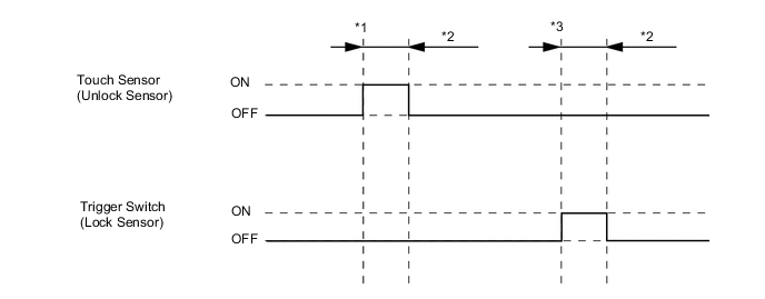
*1: With power switch off, all doors closed, electrical key transmitter sub-assembly not inside vehicle and all doors locked, front door outside handle assembly (unlock sensor) touched.
-
*2: Approximately 150 ms
-
*3: With power switch off, all doors closed, electrical key transmitter sub-assembly not inside vehicle and all doors unlocked, front door outside handle assembly (lock sensor) touched.
Main Body Tester Display Measurement Item/Range Normal Condition Diagnostic Note RR Door Courtesy SW Rear RH door courtesy light switch / ON or OFF ON: Rear RH or LH door open
OFF: Rear RH and LH door closed
- RL Door Courtesy SW Rear LH door courtesy light switch / ON or OFF ON: Rear LH or RH door open
OFF: Rear LH and RH door closed
- Back Door Courtesy SW Back door courtesy light switch / ON or OFF ON: Back door open
OFF: Back door closed
- FR Door Lock Pos Front RH door lock position switch signal / UNLOCK or LOCK UNLOCK: Front RH door unlocked
LOCK: Front RH door locked
- FR Door Courtesy Front RH door courtesy light switch signal / ON or OFF ON: Front RH door open
OFF: Front RH door closed
- FL Door Lock Pos Front LH door lock position switch signal / UNLOCK or LOCK UNLOCK: Front LH door unlocked
LOCK: Front LH door locked
- FL Door Courtesy Front LH door courtesy light switch signal / ON or OFF ON: Front LH door open
OFF: Front LH door closed
- RR-Door Lock Pos SW Rear RH door lock position switch signal / ON or OFF ON: Rear RH or LH door unlocked
OFF: Rear RH and LH door locked
- RL-Door Lock Pos SW Rear LH door lock position switch signal / ON or OFF ON: Rear LH or RH door unlocked
OFF: Rear LH and RH door locked
- -
-
-
ACTIVE TEST
Tech Tips
Using the GTS to perform Active Tests allows relays, VSVs, actuators and other items to be operated without removing any parts. This non-intrusive functional inspection can be very useful because intermittent operation may be discovered before parts or wiring is disturbed. Performing Active Tests early in troubleshooting is one way to save diagnostic time. Data List information can be displayed while performing Active Tests.
-
Connect the GTS to the DLC3.
-
Turn the power switch on (IG).
-
Turn the GTS on.
-
Enter the following menus: Body Electrical / (desired system) / Active Test.
-
According to the display on the GTS, perform the Active Test.
Entry&Start Tester Display Test Part Control Range Diagnostic Note Overhead Tuner Power Supply ON Door control receiver ON/OFF - Power for P-Seat Sens* Front door outside handle (for front passenger door) ON/OFF - *: Except Driver's Door Only Entry and Start System
Main Body Tester Display Test Part Control Range Diagnostic Note Door Lock Door lock motor Lock/Unlock - Trunk and Back-Door Open Operate back door lock motor ON or OFF - Wireless Buzzer Wireless door lock buzzer ON/OFF -
-