CAMSHAFT INSTALLATION
CAUTION / NOTICE / HINT
When replacing the injectors (including shuffling the injectors between the cylinders), common rail, intake manifold or cylinder head, it is necessary to replace the injection pipes with new ones.
When replacing the fuel supply pump, common rail, intake manifold or cylinder head, it is necessary to replace the fuel inlet pipe with a new one.
PROCEDURE
INSPECT VALVE LASH ADJUSTER ASSEMBLY
INSTALL VALVE LASH ADJUSTER ASSEMBLY
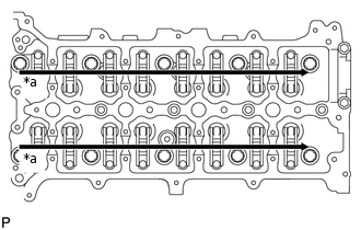
Install the 16 valve lash adjuster assemblies to the cylinder head sub-assembly.
Note:Install the valve lash adjuster assemblies to their original positions.
INSTALL NO. 1 VALVE ROCKER ARM SUB-ASSEMBLY
Install the 16 No. 1 valve rocker arm sub-assemblies to the valve lash adjuster assemblies.
INSTALL CAMSHAFT
Install the No. 2 camshaft bearing cap.
-
*a
Apply Engine Oil
Apply clean engine oil to the cam of each camshaft, journals of the cylinder head sub-assembly and No. 1 valve rocker arm sub-assemblies.
-
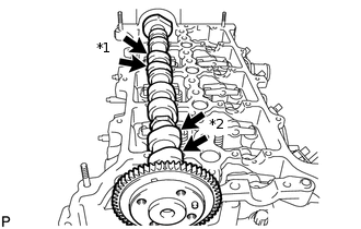
*1
No. 3 Cylinder Cam Lobe
*2
No. 1 Cylinder Cam Lobe
Place the No. 2 camshaft on the cylinder head sub-assembly as shown in the illustration so that the No. 1 cylinder cam lobe and No. 3 cylinder cam lobe face upward.
Note: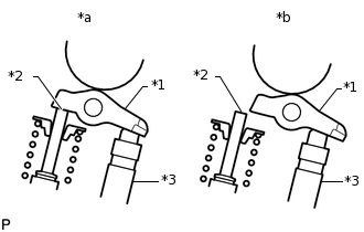
*1
No. 1 Valve Rocker Arm Sub-assembly
*2
Valve Stem
*3
Valve Lash Adjuster Assembly
*a
CORRECT
*b
INCORRECT
Before and after setting the camshaft and No. 2 camshaft on the cylinder head sub-assembly, check that the No. 1 valve rocker arm sub-assembly is firmly set to the valve lash adjuster assembly.
-
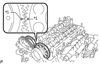
*1
Dot Mark
Align the camshaft and No. 2 camshaft timing mark (1 dot mark each).
Place the camshaft on the cylinder head sub-assembly.
-
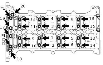
Set the 8 No. 3 camshaft bearing caps and No. 1 camshaft bearing cap on the camshafts as shown in the illustration.
Tip:Make sure of the marks and numbers on the camshaft bearing caps and place them in the proper position and direction.
Partially tighten the 20 bolts.
-
*a
Oil Pipe Seat
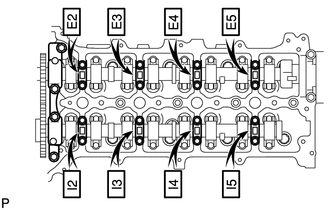
Uniformly tighten the bolts in several steps in the sequence shown in the illustration.
for 1 to 16
10 N*m
102 kgf*cm
7 ft.*lbf
for 17 to 20
21 N*m
214 kgf*cm
15 ft.*lbf
Install the 2 oil pipe seats.
17 N*m
173 kgf*cm
13 ft.*lbf
INSTALL CAMSHAFT TIMING SPROCKET
INSTALL OIL PUMP DRIVE GEAR
INSTALL NO. 1 CHAIN VIBRATION DAMPER
INSTALL CHAIN TENSIONER SLIPPER
INSTALL NO. 1 CHAIN TENSIONER ASSEMBLY
INSTALL FUEL SUPPLY PUMP ASSEMBLY
INSTALL FRONT CRANKSHAFT OIL SEAL
INSTALL TIMING CHAIN COVER SUB-ASSEMBLY
INSTALL CRANKSHAFT PULLEY
INSTALL ENGINE WATER PUMP ASSEMBLY
CONNECT CRANKSHAFT POSITION SENSOR WIRE HARNESS
INSTALL CAMSHAFT POSITION SENSOR
INSTALL OIL STRAINER SUB-ASSEMBLY
INSTALL OIL FILTER BRACKET
INSTALL OIL FILTER ELEMENT
INSTALL NO. 2 OIL PAN SUB-ASSEMBLY
INSTALL CYLINDER HEAD COVER SUB-ASSEMBLY
INSTALL NOZZLE HOLDER CLAMP SEAT
INSTALL OIL FILLER CAP SUB-ASSEMBLY
INSTALL PCV HOSE
INSTALL VACUUM TRANSMITTING HOSE ASSEMBLY
INSTALL VACUUM REGULATING VALVE ASSEMBLY
INSTALL NO. 1 VACUUM SWITCHING VALVE ASSEMBLY
INSTALL INJECTOR ASSEMBLY
INSTALL NO. 2 NOZZLE LEAKAGE PIPE
INSTALL NO. 3 FUEL HOSE
INSTALL FUEL TUBE SUB-ASSEMBLY
INSTALL FUEL HOSE PROTECTOR
INSTALL WATER INLET HOUSING
INSTALL NO. 4 WATER BY-PASS HOSE
INSTALL NO. 2 WATER BY-PASS PIPE
INSTALL NO. 1 OIL COOLER BRACKET
INSTALL NO. 1 TURBO OIL PIPE
INSTALL NO. 3 WATER BY-PASS PIPE
INSTALL NO. 8 WATER BY-PASS HOSE
INSTALL NO. 6 WATER BY-PASS HOSE
INSTALL OIL COOLER ASSEMBLY
INSTALL WATER BY-PASS HOSE
INSTALL NO. 1 CYLINDER BLOCK INSULATOR
INSTALL INTAKE MANIFOLD
INSTALL NO. 2 INTAKE MANIFOLD
INSTALL ENGINE COVER BRACKET
INSTALL GAS FILTER BRACKET
INSTALL NO. 1 GAS FILTER
INSTALL DIESEL TURBO PRESSURE SENSOR
INSTALL INTAKE MANIFOLD INSULATOR
INSTALL COMMON RAIL ASSEMBLY
INSTALL NO. 4 FUEL HOSE
INSTALL INJECTION PIPE SUB-ASSEMBLY
INSTALL FUEL INLET PIPE SUB-ASSEMBLY
INSTALL ENGINE OIL LEVEL DIPSTICK GUIDE
INSTALL ELECTRIC EGR CONTROL VALVE ASSEMBLY
INSTALL NO. 2 EGR PIPE SUB-ASSEMBLY
INSTALL EGR VALVE BRACKET
CONNECT NO. 8 WATER BY-PASS HOSE
INSTALL NO. 7 WATER BY-PASS HOSE
INSTALL DIESEL THROTTLE BODY ASSEMBLY
INSTALL V-RIBBED BELT TENSIONER ASSEMBLY
INSTALL ENGINE MOUNTING BRACKET
INSTALL NO. 4 WATER BY-PASS PIPE
INSTALL NO. 2 IDLER PULLEY SUB-ASSEMBLY
INSTALL NO. 1 IDLER PULLEY SUB-ASSEMBLY
INSTALL IDLER PULLEY COVER PLATE
INSTALL VACUUM PUMP ASSEMBLY
INSTALL GENERATOR ASSEMBLY
CONNECT ENGINE WIRE
INSTALL ENGINE ASSEMBLY
CONNECT CABLE TO NEGATIVE BATTERY TERMINAL
Note:When disconnecting the cable, some systems need to be initialized after the cable is reconnected.
Click hereClick hereClick hereClick hereClick hereClick here