OIL PUMP INSTALLATION
PROCEDURE
INSTALL OIL PUMP ASSEMBLY
Install the oil pump assembly with the 3 bolts.
21 N*m
214 kgf*cm
15 ft.*lbf
INSTALL NO. 2 OIL PAN SUB-ASSEMBLY
-
*a
Seal Packing Black
Remove any remaining seal packing and be careful not to drop any oil on the contact surfaces of the cylinder block and No. 2 oil pan sub-assembly.
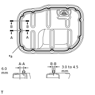
Apply seal packing in a continuous line as shown in the illustration.
Application Specification
Area
Seal Packing Diameter
Distance from Center of Bolt Hole to Center of Seal Packing
A - A
3.0 to 4.5 mm (0.118 to 0.177 in.)
6.0 mm (0.236 in.)
B - B
-
Seal Packing
Toyota Genuine Seal Packing Black, Three Bond 1207B or equivalent
Note:Remove any oil from the contact surfaces.
Install the No. 2 oil pan sub-assembly within 3 minutes and tighten the bolts within 10 minutes of applying seal packing.
Do not add engine oil for at least 2 hours after installing the No. 2 oil pan sub-assembly.
-
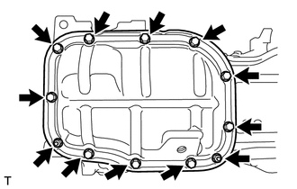
Install the No. 2 oil pan sub-assembly with the 10 bolts and 2 nuts.
10 N*m
102 kgf*cm
7 ft.*lbf
-
INSTALL OIL PAN DRAIN PLUG
INSTALL NO. 2 CHAIN SUB-ASSEMBLY
-
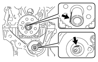
Temporarily install the crankshaft pulley bolt.
Set the crankshaft key as shown in the illustration.
Turn the drive shaft so that the cutout faces upward.
Remove the crankshaft pulley bolt.
-
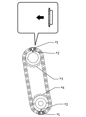
*1
Yellow Mark Plate
*2
Timing Mark
*3
Oil Pump Drive Gear
*4
Oil Pump Drive Shaft Gear

Engine Front
Align the yellow mark plates with the timing mark of each oil pump drive gear as shown in the illustration.
Install the oil pump drive gear onto the crankshaft and oil pump shaft with the No. 2 chain sub-assembly on the oil pump shaft gears.
Temporarily install the oil pump drive shaft gear with the nut.
-
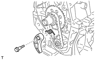
Install the spring to the chain tensioner plate, and then install the chain tensioner plate with the bolt.
10 N*m
102 kgf*cm
7 ft.*lbf
-
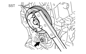
Temporarily install the crankshaft pulley with the pulley bolt.
Using SST, hold the crankshaft. Then tighten the drive shaft gear nut.
for 86 mm (3.39 in.) Bolt Pitch Type:
09213-58014
91551-80840
09330-00021
for 64 mm (2.52 in.) Bolt Pitch Type:
09213-54015
09330-00021
28 N*m
286 kgf*cm
21 ft.*lbf
Tip:For the 64 mm (2.52 in.) bolt pitch type, the part number of the installation bolt for SST (crankshaft pulley holding tool) is 91551-00850 (quantity: 2).
Remove SST, the crankshaft pulley bolt and crankshaft pulley.
-
INSTALL CRANKSHAFT TIMING SPROCKET
-
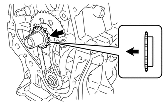
Engine Front
Install the crankshaft timing sprocket as shown in the illustration.
-
INSTALL NO. 1 CHAIN VIBRATION DAMPER
SET NO. 1 CYLINDER TO TDC/COMPRESSION
INSTALL CHAIN SUB-ASSEMBLY
INSTALL CHAIN TENSIONER SLIPPER
CHECK NO. 1 CYLINDER TO TDC/COMPRESSION
INSTALL TIMING CHAIN COVER SUB-ASSEMBLY
Install a new gasket.
Note:Remove any oil from the contact surface.
Install the water pump assembly with the 3 bolts.
21 N*m
214 kgf*cm
15 ft.*lbf
Remove any remaining packing (FIPG) material.
Note:Be careful not to drop any oil on the contact surfaces of the timing chain cover sub-assembly, cylinder head sub-assembly, camshaft housing sub-assembly, stiffening crankcase and cylinder block.
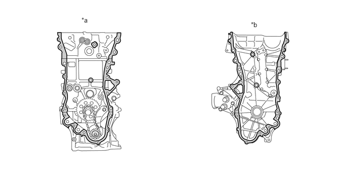
*a
Engine Side
*b
Timing Chain Cover Side

Surface to be cleaned
-
-
Install 3 new O-rings.
Apply seal packing as shown in the illustration.
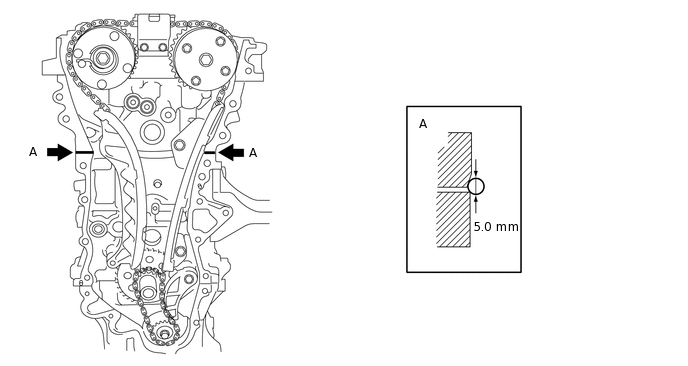
Seal packing
Toyota Genuine Seal Packing Black, Three Bond 1207B or equivalent
Standard seal diameter
5.0 mm (0.197 in.)
Note:Remove any oil from the contact surface.
Install the timing chain cover sub-assembly within 3 minutes and tighten the bolts within 10 minutes of applying seal packing.
Do not add engine oil for at least 2 hours after installing the timing chain cover sub-assembly.
Apply seal packing to the timing chain cover sub-assembly in a continuous line as shown in the following illustration.
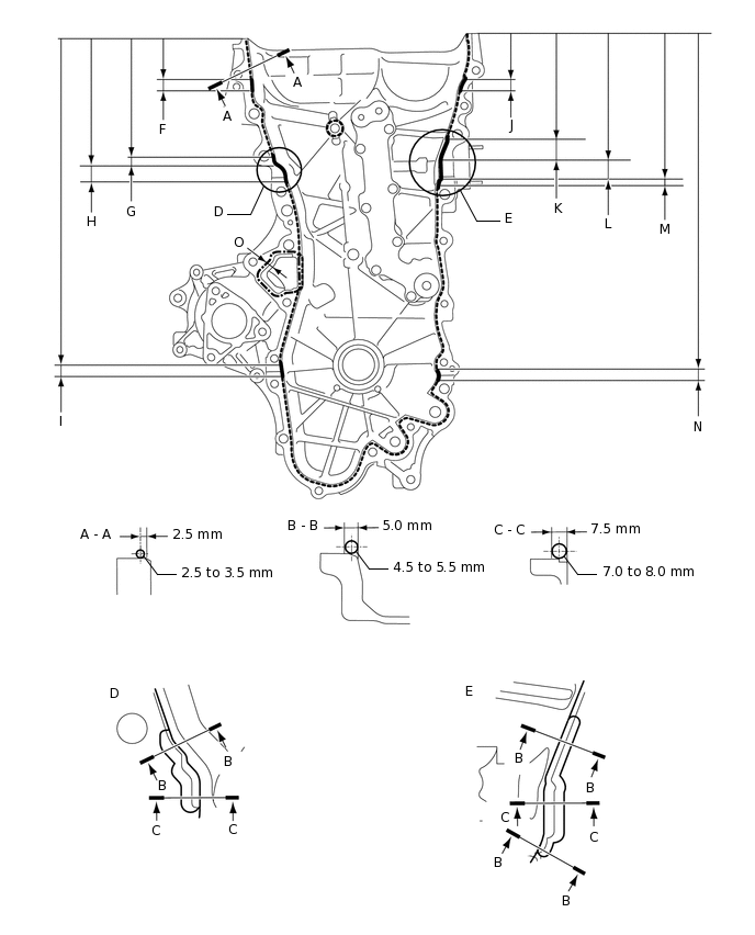
Seal Packing
Item
Seal Packing
Dashed line
Toyota Genuine Seal Packing Black, Three Bond 1207B or equivalent
Continuous line
Alternate long and short dashed line
Toyota Genuine Seal Packing 1282B, Three Bond 1282B or equivalent
Application Specification
Area
Seal Packing Diameter
Distance from Edge of Cover to:
Seal Packing Application Length
Distance from Top of Cover to Top of Seal Packing
Dashed line
2.5 to 3.0 mm (0.0984 to 0.118 in.)
Center of seal packing
2.5 mm (0.0984 in.)
-
-
Continuous line
4.5 to 5.5 mm (0.177 to 0.217 in.) or 7.0 to 8.0 mm (0.276 to 0.315 in.)
-
-
-
Alternate long and short dashed line
4.0 mm (0.157 in.)
Center of seal packing
3.0 mm (0.118 in.)
-
-
A - A
2.5 to 3.0 mm (0.0984 to 0.118 in.)
Center of seal packing
2.5 mm (0.0984 in.)
-
-
B - B
4.5 to 5.5 mm (0.177 to 0.217 in.)
Opposite edge of seal packing
5.0 mm (0.197 in.)
-
-
C - C
7.0 to 8.0 mm (0.276 to 0.315 in.)
Opposite edge of seal packing
7.5 mm (0.295 in.)
-
-
F
4.5 to 5.5 mm (0.177 to 0.217 in.)
-
15.5 mm (0.610 in.)
50.4 mm (1.98 in.)
G
4.5 to 5.5 mm (0.177 to 0.217 in.)
-
10.3 mm (0.406 in.)
143.1 mm (5.63 in.)
H
7.0 to 8.0 mm (0.276 to 0.315 in.)
-
19.5 mm (0.768 in.)
153.4 mm (6.04 in.)
I
4.5 to 5.5 mm (0.177 to 0.217 in.)
-
16.0 mm (0.630 in.)
385.8 mm (1.27 ft.)
J
4.5 to 5.5 mm (0.177 to 0.217 in.)
-
18.6 mm (0.732 in.)
51.4 mm (2.02 in.)
K
4.5 to 5.5 mm (0.177 to 0.217 in.)
-
25.3 mm (0.996 in.)
121.9 mm (4.80 in.)
L
7.0 to 8.0 mm (0.276 to 0.315 in.)
-
25.8 mm (1.02 in.)
147.2 mm (5.80 in.)
M
4.5 to 5.5 mm (0.177 to 0.217 in.)
-
5.1 mm (0.201 in.)
173.0 mm (6.81 in.)
N
4.5 to 5.5 mm (0.177 to 0.217 in.)
-
14.6 mm (0.575 in.)
385.8 mm (1.27 ft.)
O
4.0 mm (0.157 in.)
Center of seal packing
3.0 mm (0.118 in.)
-
-
Note:If there is oil on the contact surfaces, wipe them with oil-free cloth before applying seal packing.
Install the timing chain cover sub-assembly within 3 minutes and tighten the bolts within 10 minutes of applying seal packing.
After applying seal packing to the timing chain cover sub-assembly, install the engine mounting bracket and oil filter bracket within 10 minutes.
Do not add engine oil for at least 2 hours after installation.
Clean the bolts and their installation holes.
Install the timing chain cover sub-assembly.
Temporarily install the engine mounting bracket RH with the 3 bolts.
Note:Install the engine mounting bracket RH within 10 minutes of installing the timing chain cover sub-assembly.
Do not add engine oil for at least 2 hours after installation.
Install 2 new O-rings.
Temporarily tighten the oil filter bracket with the 4 bolts.
Note:Install the oil filter bracket within 10 minutes of installing the timing chain cover sub-assembly.
Do not add engine oil for at least 2 hours after installation.
-
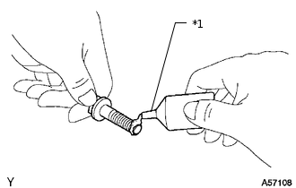
*1
Adhesive
Apply adhesive to 5 and half threads or more of the end of the bolt (E).
Adhesive
Toyota Genuine Adhesive 1324, Three Bond 1324 or equivalent
Install the timing chain cover sub-assembly with the 26 bolts and a new seal washer in the order shown in the illustration.
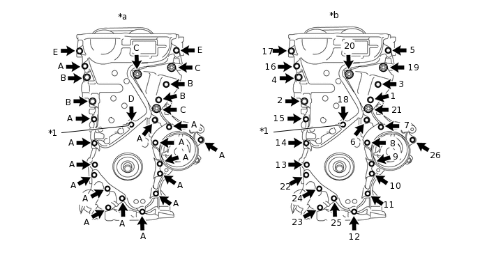
*a
Torque
*b
Bolt Tightening Order
*1
Seal Washer
-
-
Bolt A, E
26 N*m
265 kgf*cm
19 ft.*lbf
Bolt B
51 N*m
520 kgf*cm
38 ft.*lbf
Bolt C
51 N*m
520 kgf*cm
38 ft.*lbf
Bolt D
10 N*m
102 kgf*cm
7 ft.*lbf
Note:If there is oil on the contact surfaces, wipe them with oil-free cloth before applying seal packing.
Install the timing chain cover sub-assembly within 3 minutes and tighten the bolts within 10 minutes of applying seal packing.
Do not add engine oil for at least 2 hours after installation.
Bolt Length
Item
Length
Thread Diameter
Bolt A, E
35 mm (1.38 in.)
8 mm (0.315 in.)
Bolt B
55 mm (2.17 in.)
10 mm (0.394 in.)
Bolt C
80 mm (3.15 in.)
10 mm (0.394 in.)
Bolt D
40 mm (1.57 in.)
6 mm (0.236 in.)
Tip:Apply adhesive to the bolt (E) before installing it.
INSTALL TIMING CHAIN COVER OIL SEAL
INSTALL CRANKSHAFT PULLEY
INSTALL NO. 1 CHAIN TENSIONER ASSEMBLY
INSTALL SPARK PLUG TUBE GASKET
INSTALL CYLINDER HEAD COVER GASKET
INSTALL CYLINDER HEAD COVER SUB-ASSEMBLY
INSTALL IGNITION COIL ASSEMBLY
CONNECT NO. 3 WATER BY-PASS HOSE
Connect the No. 3 water by-pass hose to the water inlet housing.
INSTALL WATER INLET HOSE
INSTALL ENGINE OIL LEVEL DIPSTICK GUIDE
INSTALL DUTY VACUUM SWITCHING VALVE
INSTALL INTAKE MANIFOLD
INSTALL THROTTLE BODY ASSEMBLY
INSTALL ENGINE HANGER
REMOVE ENGINE FROM ENGINE STAND