DYNAMIC RADAR CRUISE CONTROL SYSTEM, Diagnostic DTC:P0571
| DTC Code | DTC Name |
|---|---|
| P0571 | Stop Light Switch Circuit Malfunction |
DESCRIPTION
When the brake pedal is depressed, the stop light switch sends a signal to the ECM. Upon receiving the signal, the ECM cancels cruise control. Even if there is a malfunction in the stop light signal circuit while cruise control is in operation, normal driving is maintained due to a fail-safe function.
When the brake pedal is depressed, positive voltage is applied to terminal STP of the ECM through the STOP fuse and stop light switch, and the ECM cancels cruise control.
The skid control ECU receives a signal from the driving support ECU and operates the brake control system. The skid control ECU operates the brake control system and at the same time illuminates the stop lights by operating the stop light control relay. The stop light switch assembly sends a brake pedal operation signal to the driving support ECU. After receiving the signal, the ECM performs fail-safe control by canceling the cruise control function.
DTC No. |
Detection Item |
DTC Detection Condition |
Trouble Area |
|---|---|---|---|
P0571 |
Stop Light Switch Circuit Malfunction |
The voltages of terminals ST1- and STP of the ECM are both below 1 V for 0.5 seconds or more. |
|
DTC No. |
Detection Item |
DTC Detection Condition |
Trouble Area |
|---|---|---|---|
P0571 |
Stop Light Switch Circuit Malfunction |
This trouble code is stored when the skid control ECU detects a malfunction in the stop light control relay circuit for 1 second while the dynamic radar cruise control is operating. |
|
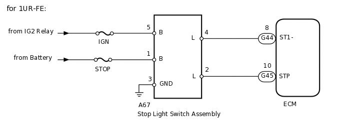
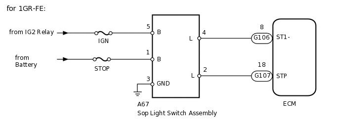
WIRING DIAGRAM
CAUTION / NOTICE / HINT
When the ECM is replaced with a new one, initialization must be performed (Click here).
Inspect the fuses for circuits related to this system before performing the following inspection procedure.
PROCEDURE
READ VALUE USING INTELLIGENT TESTER (STOP LIGHT SWITCH ASSEMBLY)
Use the Data List to check if the stop light switch is functioning properly
Powertrain > Radar Cruise > Data List
Tester Display
Measurement Item
Range
Normal Condition
Diagnostic Note
Stp Light SW M-CPU
Stop light switch (Main CPU) signal
OFF or ON
OFF: Brake pedal released
ON: Brake pedal depressed
-
OK
On screen, item changes between ON and OFF according to above chart.
Result
Result
OK
NG
NG CHECK HARNESS AND CONNECTOR (STOP LIGHT SWITCH ASSEMBLY - BATTERY AND BODY GROUND)Click here
CHECK FOR DTC (VEHICLE STABILITY CONTROL SYSTEM)
Check for DTCs
Powertrain > Radar Cruise > Trouble Codes
OK
Vehicle stability control system DTCs are not output.
Result
Result
OK
NG
CHECK FOR DTC
Clear the DTCs
Powertrain > Radar Cruise > Clear DTCs
Perform the following to make sure the DTC detection conditions are met.
Tip:If the detection conditions are not met, the system cannot detect the malfunction.
Drive the vehicle at a speed of 50 km/h (30 mph) or more.
Turn the cruise control switch on.
Push the cruise control switch to -SET to activate cruise control.
Check for DTCs
Powertrain > Radar Cruise > Trouble Codes
OK
DTC P0571 is not output.
Result
Result
Proceed to
OK
A
NG (for 1UR-FE)
B
NG (for 1GR-FE)
C
CHECK HARNESS AND CONNECTOR (STOP LIGHT SWITCH ASSEMBLY - BATTERY AND BODY GROUND)
-
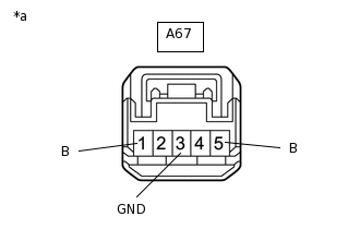
*a
Front view of wire harness connector
(to Stop Light Switch Assembly)
Disconnect the stop light switch assembly connector.
Measure the voltage according to the value(s) in the table below.
Measure the resistance according to the value(s) in the table below.
Standard Voltage
Tester Connection
Condition
Specified Condition
A67-1 (B) - Body ground
Always
11 to 14 V
A67-5 (B) - Body ground
Ignition switch ON
11 to 14 V
A67-5 (B) - Body ground
Ignition switch off
Below 1 V
Standard Resistance
Tester Connection
Condition
Specified Condition
A67-3 (GND) - Body ground
Always
Below 1 Ω
Result
Proceed to
OK
NG
NG REPAIR OR REPLACE HARNESS OR CONNECTOR
-
CHECK HARNESS AND CONNECTOR (STOP LIGHT SWITCH - ECM)
Disconnect the A67 stop light switch connector.
Disconnect the G44*1 and G45*1 or G106*2 and G107*2 ECM connectors.
*1: for 1UR-FE
*2: for 1GR-FE
Measure the resistance according to the value(s) in the table below.
Standard Resistance
Table 1. for 1UR-FE Tester Connection
Condition
Specified Condition
A67-4 (L) - G44-8 (ST1-)
Always
Below 1 Ω
A67-2 (L) - G45-18 (STP)
Always
Below 1 Ω
A67-4 (L) - Body ground
Always
10 kΩ or higher
A67-2 (L) - Body ground
Always
10 kΩ or higher
Table 2. for 1GR-FE Tester Connection
Condition
Specified Condition
A67-4 (L) - G106-8 (ST1-)
Always
Below 1 Ω
A67-2 (L) - G107-18 (STP)
Always
Below 1 Ω
A67-4 (L) - Body ground
Always
10 kΩ or higher
A67-2 (L) - Body ground
Always
10 kΩ or higher
Result
Result
OK
NG
NG REPAIR OR REPLACE HARNESS OR CONNECTOR
CHECK STOP LIGHT SWITCH ASSEMBLY
Temporarily replace the stop light switch assembly with a new or normally functioning one.
Clear the DTCs.
Powertrain > Cruise Control > Clear DTCs
Recheck for DTCs.
Powertrain > Cruise Control > Trouble Codes
Result
Result
Proceed to
OK (for 1UR-FE)
A
OK (for 1GR-FE)
B
NG
C