METER / GAUGE SYSTEM TERMINALS OF ECU
COMBINATION METER ASSEMBLY
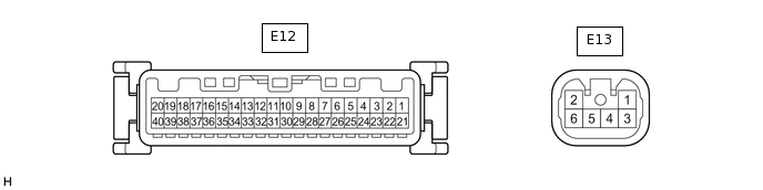
Measure the voltage and resistance according to the value(s) in the table below.
Terminal No. (Symbol)
Wiring Color
Terminal Description
Condition
Specified Condition
E13-1 (DCTY) - Body ground
P - Body ground
Driver door courtesy light switch signal
Driver door open
Below 1 V
Driver door closed
11 to 14 V
E13-2 (PCTY) - Body ground
L - Body ground
Door courtesy light switch (except driver door) signal
Any door (except driver door) open
Below 1 V
Any door (except driver door) closed
11 to 14 V
E13-3 (B) - Body ground
G - Body ground
Battery
Always
11 to 14 V
E13-4 (LL) - Body ground
Y - Body ground
LH turn indicator light signal (Output)
Ignition switch ON, LH turn indicator light off
Below 1 V
Ignition switch ON, LH turn indicator light blinking
11 to 14 V ←→ Below 1 V
E13-5 (LR) - Body ground
W - Body ground
RH turn indicator light signal (Output)
Ignition switch ON, RH turn indicator light off
Below 1 V
Ignition switch ON, RH turn indicator light blinking
11 to 14 V ←→ Below 1 V
E12-1 (HAZ) - Body ground
G - Body ground
Hazard warning signal switch signal
Ignition switch ON, hazard warning signal switch off
11 to 14 V
Ignition switch ON, hazard warning signal switch on
Below 1 V
E12-2 (EL) - Body ground
B - Body ground
LH turn indicator light signal (Input)
Ignition switch ON, LH turn signal switch off
11 to 14 V
Ignition switch ON, LH turn signal switch on
Below 1 V
E12-3 (ER) - Body ground
Y - Body ground
RH turn indicator light signal (Input)
Ignition switch ON, RH turn signal switch off
11 to 14 V
Ignition switch ON, RH turn signal switch on
Below 1 V
E12-4 (RRMT) - Body ground
V - Body ground
Rear right seat belt warning output signal
Ignition switch ON, rear seat belt warning light RH off
11 to 14 V
Ignition switch ON, rear seat belt warning light RH on
Below 1 V
E12-5 (RLMT) - Body ground
SB - Body ground
Rear left seat belt warning output signal
Ignition switch ON, rear seat belt warning light LH off
11 to 14 V
Ignition switch ON, rear seat belt warning light LH on
Below 1 V
E12-8 (SW) - Body ground
V - Body ground
Brake fluid level signal
Ignition switch ON, brake fluid level not low
11 to 14 V
Ignition switch ON, brake fluid level low
Below 1 V
E12-9 (ACC) - Body ground
GR - Body ground
ACC switch signal
Ignition switch off
Below 1 V
Ignition switch ACC
11 to 14 V
E12-10 (PKBI) - Body ground
R - Body ground
Parking brake switch signal
Parking brake applied
Below 1 V
Parking brake released
11 to 14 V
E12-11 (RRSB) - Body ground
V - Body ground
Rear right seat belt buckle switch signal
Ignition switch ON, rear seat belt RH unfastened
Below 1 V
Ignition switch ON, rear seat belt RH fastened
11 to 14 V
E12-12 (RLSB) - Body ground
SB - Body ground
Rear left seat belt buckle switch signal
Ignition switch ON, rear seat belt LH unfastened
Below 1 V
Ignition switch ON, rear seat belt LH fastened
11 to 14 V
E12-13 (P/SB) - Body ground
B - Body ground
Front passenger seat belt buckle switch signal
Ignition switch ON, front passenger seat occupied, and front passenger seat belt unfastened
Below 1 V
Ignition switch ON, front passenger seat occupied, and front passenger seat belt fastened
11 to 14 V
E12-14 (BKL) - Body ground
W - Body ground
Driver seat belt buckle switch signal
Ignition switch ON, driver seat belt unfastened
Below 1 V
Ignition switch ON, driver seat belt fastened
11 to 14 V
E12-17 (TX1+) - E12-18 (TX1-)
L - G
Ambient temperature sensor signal
Ignition switch ON
0.5 to 4 V
E12-19 (CHG-) - Body ground*4
BE - Body ground
Charge warning light signal
Engine running, charge warning light off
11 to 14 V
Engine running, charge warning light on
Below 1 V
E12-20 (S) - Body ground*5
G - Body ground
Oil pressure signal
Engine started
11 to 14 V
Engine not started
Below 1 V
E12-21 (SI) - Body ground
Y - Body ground
Speed signal for other system (Input)
Ignition switch ON, wheel being rotated
Pulse generation (See waveform 1)
E12-22 (+S) - Body ground
V - Body ground
Speed signal for other system (Output)
Ignition switch ON, wheel being rotated
Pulse generation (See waveform 1)
E12-23 (CHK) - Body ground*2
GR - Body ground
MIL (Check engine warning light) signal
Ignition switch ON, MIL off
11 to 14 V
Ignition switch ON, MIL on
Below 1 V
E12-24 (FOG) - Body ground*3
LG - Body ground
Front fog light signal
Ignition switch ON, front fog indicator light off
Below 1 V
Ignition switch ON, front fog indicator light on
11 to 14 V
E12-25 (ILL+) - Body ground
G - Body ground
Taillight signal
Ignition switch ON, tail indicator light off
Below 1 V
Ignition switch ON, tail indicator light on
11 to 14 V
E12-28 (+) - Body ground
BR - Body ground
High beam signal
High beam off
Below 1 V
High beam on
11 to 14 V
E12-29 (-) - Body ground
W-B - Body ground
Ground
Always
Below 1 Ω
E12-30 (SW) - Body ground
L - Body ground
Turn signal switch signal
Ignition switch ON, LH and RH turn signal switch off
11 to 14 V
Ignition switch ON, LH or RH turn signal switch on
Below 1 V
E12-31 (TX+) - Body ground*1
W - Body ground
TCM communication line
Ignition switch ON
Pulse generation (See waveform 2)
E12-32 (BRQ) - Body ground*1
LG - Body ground
TCM communication line
Always
Below 1.44 V
E12-33 (S) - Body ground
G - Body ground
Rear fog light signal
Ignition switch ON, rear fog indicator light off
Below 1 V
Ignition switch ON, rear fog indicator light on
11 to 14 V
E12-34 (L) - E12-35 (ES)
V - GR
Fuel level signal
Ignition switch ON, fuel level full
Below 1 V
Ignition switch ON, fuel level low (fuel level warning light on)
4.5 to 9 V
E12-36 (CANL) - Body ground
W - Body ground
CAN communication line
-
-
E12-37 (CANH) - Body ground
LG - Body ground
CAN communication line
-
-
E12-38 (ET) - Body ground
W-B - Body ground
Ground
Always
Below 1 Ω
E12-39 (IG+) - Body ground
P - Body ground
Ignition switch signal
Ignition switch off
Below 1 V
Ignition switch ON
11 to 14 V
E12-40 (B) - Body ground
L - Body ground
Battery
Always
11 to 14 V
*1: for Multi-mode Manual Transaxle
*2: for 1PP
*3: w/ Front Fog Light
*4: w/o Stop and Start System
*5: for 1KR-FE
-
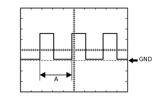
Waveform 1 (Reference):
Item
Condition
Tool setting
5 V/DIV., 20 ms./DIV.
Vehicle condition
Ignition switch ON, wheel being rotated
Tip:When the system is functioning normally, one wheel revolution generates 4 pulses. As the vehicle speed increases, the width indicated by (A) in the illustration narrows.
-
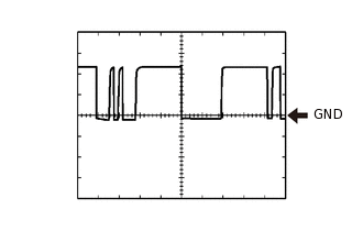
Waveform 2 (Reference):
Item
Condition
Tool setting
2 V/DIV., 500 μs./DIV.
Vehicle condition
Ignition switch ON