ENGINE IMMOBILISER SYSTEM(w/o Entry and Start System) TERMINALS OF ECU
-
CHECK TRANSPONDER KEY AMPLIFIER

-
Disconnect the D54 transponder key amplifier connector.
-
Measure the resistance and voltage, and check for pulses according to the value(s) in the table below.
Terminal No. (Symbol) Input/Output Wiring Color Terminal Description Condition Specified Condition D54-7 (AGND) - Body ground - GR - Body ground Ground Always Below 1 Ω -
Reconnect the D54 transponder key amplifier connector.
-
Measure the voltage and check for pulses according to the value(s) in the table below.
Terminal No. (Symbol) Input/Output Wiring Color Terminal Description Condition Specified Condition D54-1 (VC5) - D54-7 (AGND) Input R - GR Transponder key amplifier power supply Ignition switch ON 4.5 to 5.5 V D54-4 (CODE) - D54-7 (AGND) Output LG - GR Demodulated signal of key code data Key inserted in ignition key cylinder Pulse generation D54-5 (TXCT) - D54-7 (AGND) Output W-G - GR Key code output signal No key in ignition key cylinder Below 1 V Key inserted in ignition key cylinder Pulse generation
-
-
CHECK INSTRUMENT PANEL JUNCTION BLOCK ASSEMBLY AND MAIN BODY ECU (NETWORK GATEWAY ECU)
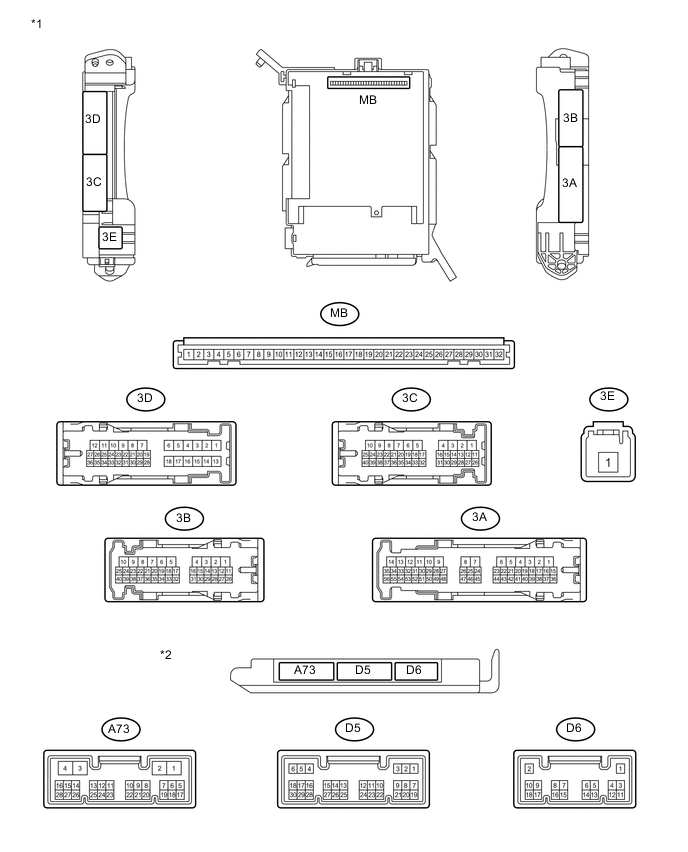
Text in Illustration *1 Instrument Panel Junction Block Assembly *2 Main Body ECU (Network Gateway ECU)
-
Remove the main body ECU (network gateway ECU) from the instrument panel junction block assembly.
-
Disconnect the D5, D6 and A73 main body ECU (network gateway ECU) connectors.
-
Measure the resistance and voltage according to the value(s) in the table below.
Terminal No. (Symbol) Input/Output Wiring Color Terminal Description Condition Specified Condition MB-1 (BECU) - Body ground Input None - Body ground Battery power supply Always 11 to 14 V MB-8 (IG) - Body ground Input None - Body ground Ignition switch power supply Ignition switch ON 11 to 14 V Ignition switch off Below 1 V MB-9 (ACC) - Body ground Input None - Body ground ACC power supply Ignition switch ACC 11 to 14 V Ignition switch off Below 1 V MB-11 (GND) - Body ground - None - Body ground Ground Always Below 1 Ω MB-32 (BMPX) - Body ground Input None - Body ground Battery power supply Always 11 to 14 V D5-22 (KSW) - Body ground Input BR - Body ground Unlock warning switch input No key in ignition key cylinder (off) Below 1 V Key inserted ignition key cylinder (on) 11 to 14 V D6-1 (GND) - Body ground - B - Body ground Ground Always Below 1 Ω A73-4 (GND) - Body ground - B-Y - Body ground Ground Always Below 1 Ω -
Reconnect the D5, D6 and A73 main body ECU (network gateway ECU) connectors.
-
Install the main body ECU (network gateway ECU) to the instrument panel junction block assembly.
-
Measure the resistance and voltage, and check for pulses according to the value(s) in the table below.
Terminal No. (Symbol) Input/Output Wiring Color Terminal Description Condition Specified Condition A73-5 (CODE) - Body ground Input LG - Body ground Demodulated signal of key code data Key inserted in ignition key cylinder Pulse generation A73-9 (IMO) - Body ground Input / output Y - Body ground EFI communication Ignition switch off Below 1 V Ignition switch ON Pulse generation A73-8 (VC5) - Body ground Output R - Body ground Transponder key amplifier power supply Ignition switch ON 4.5 to 5.5 V A73-15 (TXCT) - Body ground Input W - Body ground Key code output signal Key inserted in ignition key cylinder Pulse generation A73-16 (AGND) - Body ground - GR - Body ground Transponder key amplifier ground Always Below 1 Ω A73-17 (UART) - Body ground* Input / output SB - Body ground Transponder key ECU communication Key inserted in ignition key cylinder Pulse generation
-
*: w/ Transponder Key ECU Assembly
-
-
-
CHECK TRANSPONDER KEY ECU ASSEMBLY
-
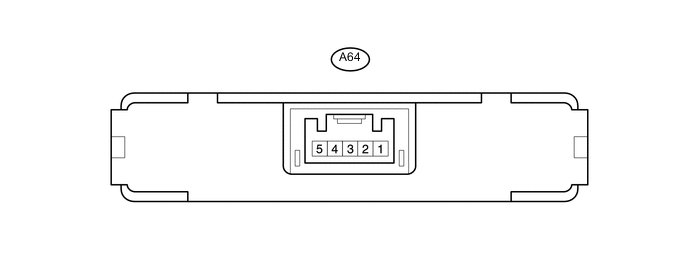
Disconnect the A64 transponder key ECU assembly connector.
-
Measure the resistance and voltage according to the value(s) in the table below.
Terminal No. (Symbol) Input/Output Wiring Color Terminal Description Condition Specified Condition A64-1 (+B) - Body ground Input L-R - Body ground Battery power supply Always 11 to 14 V A64-5 (GND) - Body ground - B-Y - Body ground Ground Always Below 1 Ω -
Reconnect the A64 transponder key ECU assembly connector.
-
Measure the voltage and check for pulses according to the value(s) in the table below.
Terminal No. (Symbol) Input/Output Wiring Color Terminal Description Condition Specified Condition A64-3 (UART) - A64-5 (GND) Input/Output SB - B-Y Main body ECU communication Key inserted in ignition key cylinder Pulse generation
-
-
CHECK ECM
-
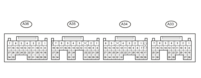
Measure the resistance and voltage, and check for pulses according to the value(s) in the table below.
Terminal No. (Symbol) Input/Output Wiring Color Terminal Description Condition Specified Condition A33-1 (+B2) - A36-4 (E01) Input V - B-L Battery power supply Ignition switch off Below 1 V Ignition switch ON 11 to 14 V A33-2 (BATT) - A36-4 (E01) Input W - B-L Battery power supply Always 11 to 14 V A34-6 (+B) - A36-4 (E01) Input V - B-L Battery power supply Ignition switch off Below 1 V Ignition switch ON 11 to 14 V A35-25 (IMO) - A36-4 (E01) Input/Output Y - B-L Main body ECU communication Ignition switch off Below 1 V Ignition switch ON Pulse generation A36-4 (E01) - Body ground - B-L - Body ground Ground Always Below 1 Ω
-