CAMSHAFT(w/o Glow Plug Controller) INSTALLATION
PROCEDURE
INSTALL CAMSHAFT
-
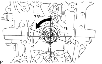
*1
Key
*a
TDC Mark
Turn the crankshaft to set the key in the BTDC 75° position.
Apply engine oil to each camshaft journal and cam.
-
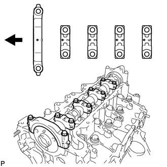

Engine Front
Examine the front marks and numbers of the camshaft bearing caps, and check that the order is as shown in the illustration. Then, temporarily install the No. 1 camshaft bearing cap and 4 No. 2 camshaft bearing caps with the 10 bolts.
Note:Do not tilt the valve rocker arm sub-assemblies when installing the camshaft onto the cylinder head sub-assembly.
-
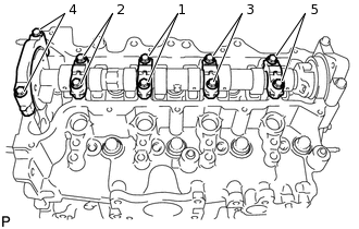
Using several steps, temporarily tighten the 10 bolts, and then tighten them to the specified torque in the order shown in the illustration.
19 N*m
194 kgf*cm
14 ft.*lbf
-
INSTALL CHAIN SUB-ASSEMBLY
INSTALL NO. 1 CHAIN VIBRATION DAMPER
INSTALL CHAIN TENSIONER SLIPPER
INSTALL NO. 1 CHAIN TENSIONER ASSEMBLY
INSTALL TIMING CHAIN COVER SUB-ASSEMBLY
CONNECT INLET WATER HOSE LH
Connect the inlet water hose LH.
Tip:The clip on the inlet water housing side can be installed with any orientation, as long as it does not contact any of the surrounding parts.
INSTALL CRANKSHAFT DAMPER SUB-ASSEMBLY
INSTALL NO. 2 TIMING CHAIN COVER
INSTALL ENGINE MOUNTING BRACKET RH
CHECK VALVE CLEARANCE
ADJUST VALVE CLEARANCE
INSTALL CYLINDER HEAD COVER SUB-ASSEMBLY
INSTALL HARNESS BRACKET
INSTALL V-RIBBED BELT TENSIONER ASSEMBLY
INSTALL VACUUM PUMP ASSEMBLY
INSTALL CAMSHAFT POSITION SENSOR (w/o Stop And Start System)
-
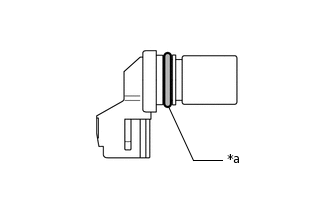
*a
O-ring
Apply a light coat of engine oil to the O-ring of the camshaft position sensor.
Note:If reusing the camshaft position sensor, be sure to inspect the O-ring.
Install the camshaft position sensor with the bolt.
7.0 N*m
71 kgf*cm
62 in.*lbf
Note:If the camshaft position sensor has been dropped or subjected to a strong impact, replace it.
Make sure that the O-ring is not cracked or moved out of place during installation.
-
INSTALL NO. 2 CYLINDER HEAD COVER
INSTALL WATER BY-PASS PIPE SUB-ASSEMBLY
Install a new O-ring to the water by-pass pipe sub-assembly.
Note:Apply water to the water inlet housing O-ring fitting surface before installing the water by-pass pipe sub-assembly.
-
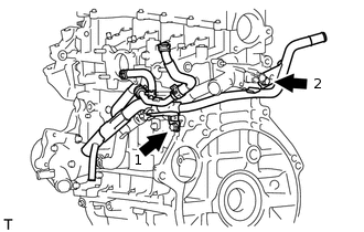
Install the water by-pass pipe sub-assembly with the 2 bolts in the order shown in the illustration.
9.0 N*m
92 kgf*cm
80 in.*lbf
-
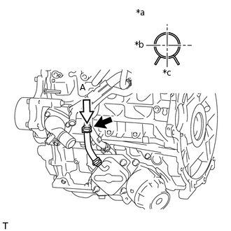
*a
View A
*b
Front
*c
LH
Connect the oil cooler hose.
-

*a
Upper
*b
View A
Connect the water by-pass hose.
INSTALL NO. 4 WATER BY-PASS HOSE
INSTALL NO. 2 OIL COOLER HOSE
INSTALL NO. 1 SUPPLY PUMP DRIVE COUPLING
TEMPORARILY INSTALL SUPPLY PUMP ASSEMBLY
INSTALL FUEL INLET PIPE SUB-ASSEMBLY
CONNECT NO. 2 FUEL HOSE
Connect the No. 2 fuel hose to the supply pump assembly.
INSTALL NOZZLE LEAKAGE PIPE ASSEMBLY
INSTALL NOZZLE LEAKAGE PIPE SET CLAMP
INSTALL INTAKE AIR CONNECTOR WITH DIESEL THROTTLE BODY
INSTALL ENGINE OIL LEVEL DIPSTICK GUIDE
INSTALL ENGINE OIL LEVEL DIPSTICK
INSTALL EGR VALVE (ELECTRIC EGR CONTROL VALVE ASSEMBLY)
INSTALL HARNESS BRACKET
INSTALL NO. 1 EGR COOLER BRACKET
INSTALL EGR WITH COOLER PIPE ASSEMBLY
INSTALL GENERATOR BRACKET
INSTALL GENERATOR ASSEMBLY
INSTALL ENGINE COVER BRACKET (w/ No. 1 Engine Cover)
REMOVE ENGINE STAND