FRONT DIFFERENTIAL CARRIER ASSEMBLY REASSEMBLY
PROCEDURE
INSTALL FRONT DIFFERENTIAL SIDE GEAR SHAFT BEARING RH
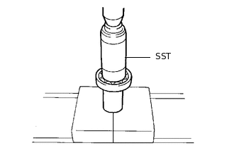
Using SST and a press, press in the shaft bearing.
09223-00010
Using a snap ring expander, install the snap ring.
Tip:Install the snap ring securely.
INSTALL DIFFERENTIAL SIDE GEAR SHAFT SUB-ASSEMBLY RH
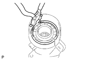
Install the shaft to the differential tube.
Using needle nose pliers, install the snap ring.
Tip:Install the snap ring securely.
INSTALL DIFFERENTIAL SIDE GEAR SHAFT OIL SEAL
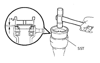
*a
Oil Seal Depth
Coat the lip of a new oil seal with MP grease.
Standard oil seal depth
4.8 to 5.8 mm (0.189 to 0.228 in.)
Using SST and a plastic-faced hammer, tap in the oil seal.
09223-15020
INSTALL DIFFERENTIAL CASE ASSEMBLY
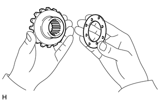
Install the 2 thrust washers to the 2 side gears.
Standard Thrust Washer
Thickness
Thickness
1.48 to 1.52 mm (0.0583 to 0.0598 in.)
1.73 to 1.77 mm (0.0682 to 0.0696 in.)
1.53 to 1.57 mm (0.0603 to 0.0618 in.)
1.78 to 1.82 mm (0.0701 to 0.0716 in.)
1.58 to 1.62 mm (0.0622 to 0.0637 in.)
1.83 to 1.87 mm (0.0721 to 0.0736 in.)
1.63 to 1.67 mm (0.0642 to 0.0657 in.)
1.88 to 1.92 mm (0.0741 to 0.0755 in.)
1.68 to 1.72 mm (0.0662 to 0.0677 in.)
-
-
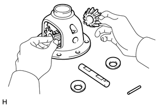
Install the 2 side gears, 2 pinion gears, 2 side gear thrust washers, 2 pinion thrust washers and pinion shaft to the differential case.
Tip:Align the holes of the differential case and pinion shaft.
-
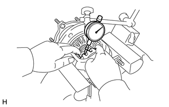
Measure the side gear backlash.
Using a dial indicator, measure the side gear backlash while holding one pinion gear toward the differential case.
Standard backlash
0.15 mm (0.00591 in.) or less
If the backlash is not as specified, install 2 side gear thrust washers with different thicknesses.
-
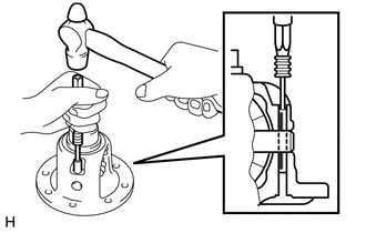
Using a 5 mm pin punch and hammer, tap in the straight pin through the differential case and hole of the pinion shaft.
Stake the differential case.
INSTALL DIFFERENTIAL RING GEAR
Clean the contact surfaces of the differential case and ring gear.
Heat the ring gear in water that is approximately 100°C (212°F).
Carefully remove the ring gear from the boiling water.
After the moisture on the ring gear has completely evaporated, quickly install the ring gear to the differential case.
-
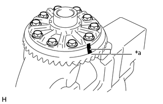
*a
Matchmark
Align the matchmarks on the ring gear with those of the differential case.
After the ring gear cools down, apply thread lock adhesive to the 10 set bolts and install them.
Adhesive
Toyota Genuine Adhesive 1360K, Three Bond 1360K or equivalent
115 N*m
1173 kgf*cm
85 ft.*lbf
INSTALL FRONT DIFFERENTIAL CASE BEARING
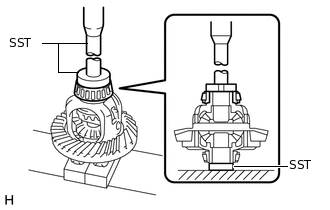
Using SST and a press, press the 2 bearings (inner) into the differential case.
09950-60010
09951-00520
09951-00610
09950-70010
09951-07150
INSTALL FRONT DIFFERENTIAL CASE BEARING
Tip:When replacing the 3 differential case bearings, install the 2 thinnest new front differential case plate washers onto each bearing. When reusing the bearings, install the new front differential case plate washers to the same places they were removed from.
-
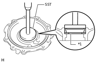
*1
Front Differential Case Plate Washer
Using SST and a press, press the case bearing (outer race) into the differential case bearing retainer.
09950-60020
09951-00810
09950-70010
09951-07150
-
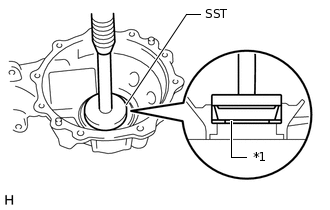
*1
Front Differential Case Plate Washer
Using SST and a press, press the case bearing (outer) into the differential carrier.
09950-60020
09951-00810
09950-70010
09951-07150
-
INSTALL FRONT DRIVE PINION REAR TAPERED ROLLER BEARING (OUTER)
-
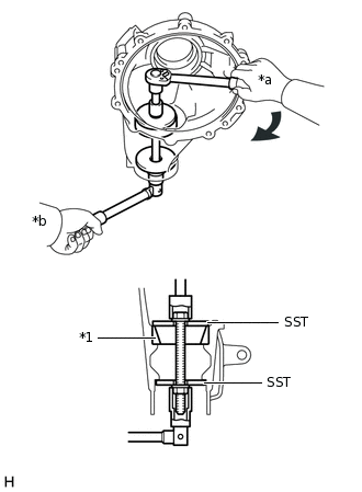
*1
Front Drive Pinion Rear Tapered Roller Bearing (Outer)
*a
Turn
*b
Hold
Using SST, install the front drive pinion rear tapered roller bearing (outer race).
09950-60020
09951-00720
09951-00890
-
INSTALL FRONT DRIVE PINION FRONT TAPERED ROLLER BEARING
Using a brass bar and hammer, tap in the oil storage ring.
-
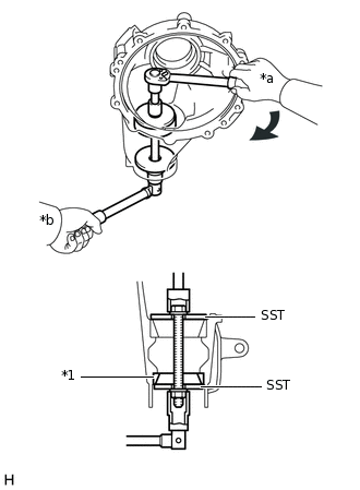
*1
Front Drive Pinion Front Tapered Roller Bearing (Outer)
*a
Turn
*b
Hold
Using SST, install the front drive pinion front tapered roller bearing (outer race).
09950-60020
09951-00720
09951-00890
INSTALL FRONT DRIVE PINION FRONT TAPERED ROLLER BEARING
-
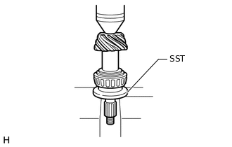
Install the washer to the drive pinion.
Tip:First, install a washer that has the same thickness as the removed washer, and then check the tooth contact pattern. Replace the washer with one of a different thickness if necessary.
Using SST and a press, press the front bearing onto the drive pinion.
09506-30012
-
INSPECT DIFFERENTIAL DRIVE PINION PRELOAD
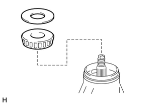
Install the drive pinion, roller bearing and oil slinger to the differential case.
Tip:Install the spacer, oil storage ring and oil seal after adjusting the gear contact pattern.
-
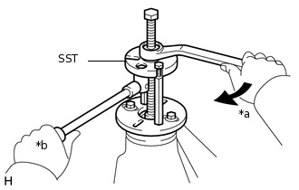
*a
Turn
*b
Hold
Using SST, install the companion flange.
09950-30012
09951-03010
09953-03010
09954-03010
09955-03030
09956-03020
Note:Before using SST (center bolt), apply hypoid gear oil to its threads and tip.
Adjust the drive pinion preload by tightening the companion flange nut.
-
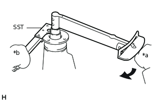
*a
Turn
*b
Hold
Using SST to hold the companion flange in place, then slowly tighten the nut within the drive pinion preload adjustment range so that it reaches the specified drive pinion preload (at Starting).
09330-00021
09330-00030
Limit Torque Value
370 N*m (3773 kgf*cm, 273 ft.*lbf) or less
Note:As there is no spacer, tighten the nut a little at a time. Be careful not to overtighten it.
Apply hypoid gear oil LSD to the nut.
-
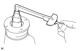
Using a torque wrench, measure the preload.
Standard Preload (at Starting)
Item
Specified Condition
New bearing
0.98 to 1.92 N*m (10 to 19 kgf*cm, 9 to 16 in.*lbf)
Used bearing
0.49 to 0.78 N*m (5 to 7 kgf*cm, 5 to 6 in.*lbf)
Note:For a more accurate measurement, rotate the bearing forward and backward several times before measuring.
INSTALL DIFFERENTIAL CASE ASSEMBLY
ADJUST DIFFERENTIAL RING GEAR BACKLASH
Install the side bearing retainer with the 10 bolts.
75 N*m
765 kgf*cm
55 ft.*lbf
-
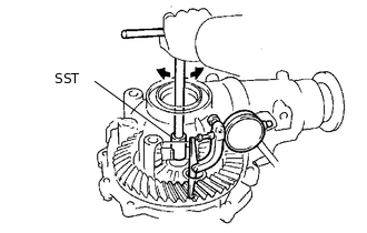
Using SST and a dial indicator, measure the ring gear backlash.
09564-32011
Standard backlash
0.11 to 0.21 mm (0.00433 to 0.00826 in.)
If the backlash is not as specified, adjust it by either increasing or decreasing the number of washers on both sides equally.
Tip:There should be no clearance between the plate washer and case. Make sure that the ring gear has backlash.
Standard Washer LH Thickness (Side Opposite Ring Gear)
Part No.
Thickness mm (in.)
Part No.
Thickness
90564-50184
1.57 to 1.59 (0.0619 to 0.0625)
90564-50136
1.95 to 1.97 (0.0768 to 0.0775)
90564-50124
1.59 to 1.61 (0.0626 to 0.0633)
90564-50197
1.97 to 1.99 (0.0776 to 0.0783)
90564-50185
1.61 to 1.63 (0.0634 to 0.0641)
90564-50198
1.99 to 2.01 (0.0784 to 0.0791)
90564-50186
1.63 to 1.65 (0.0642 to 0.0649)
90564-50138
2.01 to 2.03 (0.0792 to 0.0799)
90564-50126
1.65 to 1.67 (0.0650 to 0.0657)
90564-50199
2.03 to 2.05 (0.0800 to 0.0807)
90564-50187
1.67 to 1.69 (0.0658 to 0.0665)
90564-50200
2.05 to 2.07 (0.0808 to 0.0814)
90564-50188
1.69 to 1.71 (0.0666 to 0.0673)
90564-50140
2.07 to 2.09 (0.0815 to 0.0822)
90564-50128
1.71 to 1.73 (0.0674 to 0.0681)
90564-50201
2.09 to 2.11 (0.0823 to 0.0830)
90564-50189
1.73 to 1.75 (0.0682 to 0.0688)
90564-50202
2.11 to 2.13 (0.0831 to 0.0838)
90564-50190
1.75 to 1.77 (0.0689 to 0.0696)
90564-50142
2.13 to 2.15 (0.0839 to 0.0846)
90564-50130
1.77 to 1.79 (0.0697 to 0.0704)
90564-50203
2.15 to 2.17 (0.0847 to 0.0854)
90564-50191
1.79 to 1.81 (0.0705 to 0.0712)
90564-50231
2.17 to 2.19 (0.0855 to 0.0862)
90564-50192
1.81 to 1.83 (0.0713 to 0.0720)
90564-50232
2.19 to 2.21 (0.0863 to 0.0870)
90564-50132
1.83 to 1.85 (0.0721 to 0.0728)
90564-50233
2.21 to 2.23 (0.0871 to 0.0877)
90564-50193
1.85 to 1.87 (0.0729 to 0.0736)
90564-50234
2.23 to 2.25 (0.0878 to 0.0885)
90564-50194
1.87 to 1.89 (0.0737 to 0.0744)
90564-50235
2.25 to 2.27 (0.0886 to 0.0893)
90564-50134
1.89 to 1.91 (0.0745 to 0.0751)
90564-50236
2.27 to 2.29 (0.0894 to 0.0901)
90564-50195
1.91 to 1.93 (0.0752 to 0.0759)
90564-50237
2.29 to 2.31 (0.0902 to 0.0909)
90564-50196
1.93 to 1.95 (0.0760 to 0.0767)
-
-
Table 1. Standard Washer RH Thickness (ring gear side): Part No.
Thickness mm (in.)
Part No.
Thickness mm (in.)
90564-50224
1.43 to 1.45 (0.0563 to 0.0570)
90564-50212
1.81 to 1.83 (0.0713 to 0.0720)
90564-50225
1.45 to 1.47 (0.0571 to 0.0578)
90564-50162
1.83 to 1.85 (0.0721 to 0.0728)
90564-50226
1.47 to 1.49 (0.0579 to 0.0586)
90564-50213
1.85 to 1.87 (0.0729 to 0.0736)
90564-50227
1.49 to 1.51 (0.0587 to 0.0594)
90564-50214
1.87 to 1.89 (0.0737 to 0.0744)
90564-50228
1.51 to 1.53 (0.0595 to 0.0602)
90564-50164
1.89 to 1.91 (0.0745 to 0.0751)
90564-50229
1.53 to 1.55 (0.0603 to 0.0610)
90564-50215
1.91 to 1.93 (0.0752 to 0.0759)
90564-50230
1.55 to 1.57 (0.0611 to 0.0618)
90564-50216
1.93 to 1.95 (0.0760 to 0.0767)
90564-50204
1.57 to 1.59 (0.0619 to 0.0625)
90564-50166
1.95 to 1.97 (0.0768 to 0.0775)
90564-50154
1.59 to 1.61 (0.0626 to 0.0633)
90564-50217
1.97 to 1.99 (0.0776 to 0.0783)
90564-50205
1.61 to 1.63 (0.0634 to 0.0641)
90564-50218
1.99 to 2.01 (0.0784 to 0.0791)
90564-50206
1.63 to 1.65 (0.0642 to 0.0649)
90564-50168
2.01 to 2.03 (0.0792 to 0.0799)
90564-50156
1.65 to 1.67 (0.0650 to 0.0657)
90564-50219
2.03 to 2.05 (0.0800 to 0.0807)
90564-50207
1.67 to 1.69 (0.0658 to 0.0665)
90564-50220
2.05 to 2.07 (0.0808 to 0.0814)
90564-50208
1.69 to 1.71 (0.0666 to 0.0673)
90564-50170
2.07 to 2.09 (0.0815 to 0.0822)
90564-50158
1.71 to 1.73 (0.0674 to 0.0681)
90564-50221
2.09 to 2.11 (0.0823 to 0.0830)
90564-50209
1.73 to 1.75 (0.0682 to 0.0688)
90564-50222
2.11 to 2.13 (0.0831 to 0.0838)
90564-50210
1.75 to 1.77 (0.0689 to 0.0696)
90564-50172
2.13 to 2.15 (0.0839 to 0.0846)
90564-50160
1.77 to 1.79 (0.0697 to 0.0704)
90564-50223
2.15 to 2.17 (0.0847 to 0.0854)
90564-50211
1.79 to 1.81 (0.0705 to 0.0712)
-
-
INSPECT TOTAL PRELOAD
Using a torque wrench, measure the preload with the teeth of the drive pinion and ring gear in contact.
Standard Total Preload (at Starting)
Item
Specified Condition
New bearing
1.2 to 2.8 N*m (13 to 28 kgf*cm, 11 to 24 in.*lbf)
Used bearing
0.71 to 1.66 N*m (8 to 16 kgf*cm, 7 to 14 in.*lbf)
If necessary, disassemble and inspect the differential.
ADJUST TOOTH CONTACT BETWEEN RING GEAR AND DRIVE PINION
Remove the differential case bearing retainer and differential case.
-
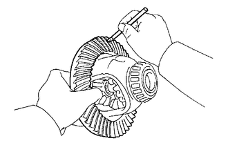
Coat 3 or 4 teeth at 3 different positions on the ring gear with Prussian blue.
Install the differential case and differential case bearing retainer.
75 N*m
765 kgf*cm
55 ft.*lbf
Hold the companion flange firmly in place and rotate the ring gear in both directions.
Remove the differential case bearing retainer and differential case.
Inspect the tooth contact pattern.
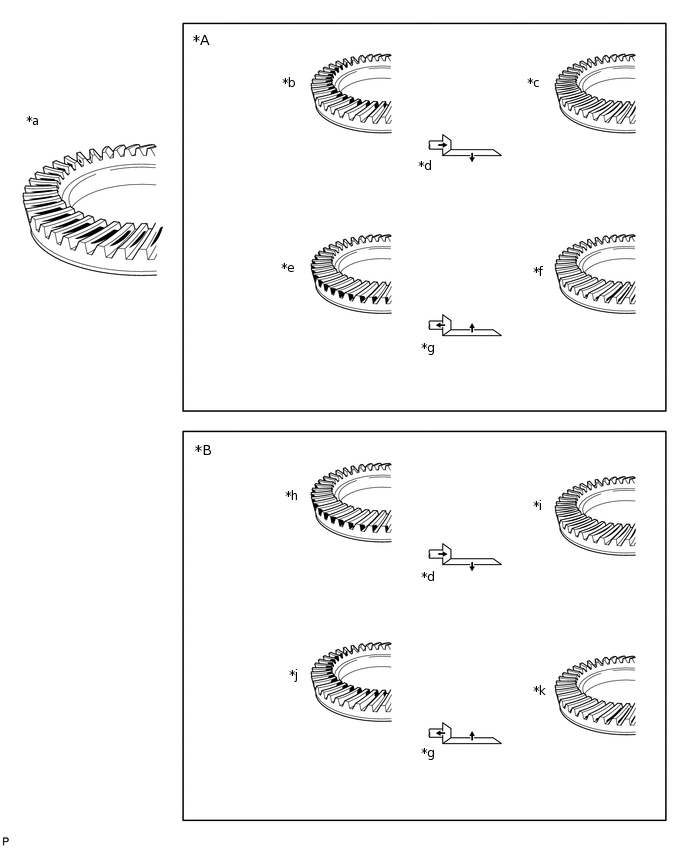
*A
Drive Side
*B
Coast Side
*a
Proper Contact
*b
Toe Contact
*c
Face Contact
*d
Select an adjusting washer that will shift the drive pinion closer to the ring gear.
*e
Heel Contact
*f
Flank Contact
*g
Select an adjusting washer that will shift the drive pinion away from the ring gear.
*h
Heel Contact
*i
Flank Contact
*j
Toe Contact
*k
Face Contact
-
-
-
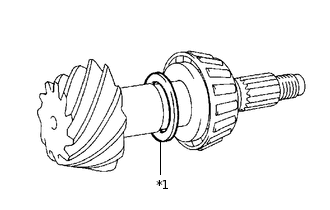
*1
Drive Pinion Washer
If the teeth are not contacting properly, use the following chart to select an appropriate washer.
Standard Washer
Part No.
Thickness mm (in.)
Part No.
Thickness mm (in.)
90564-35109
1.69 to 1.71 (0.0666 to 0.0673)
90564-35120
2.02 to 2.04 (0.0796 to 0.0803)
90564-35110
1.72 to 1.74 (0.0678 to 0.0685)
90564-35121
2.05 to 2.07 (0.0807 to 0.0814)
90564-35111
1.75 to 1.77 (0.0689 to 0.0696)
90564-35123
2.08 to 2.10 (0.0819 to 0.0826)
90564-35112
1.78 to 1.80 (0.0701 to 0.0708)
90564-35124
2.11 to 2.13 (0.0831 to 0.0838)
90564-35113
1.81 to 1.83 (0.0713 to 0.0720)
90564-35125
2.14 to 2.16 (0.0843 to 0.0850)
90564-35114
1.84 to 1.86 (0.0725 to 0.0732)
90564-35126
2.17 to 2.19 (0.0855 to 0.0862)
90564-35115
1.87 to 1.89 (0.0737 to 0.0744)
90564-35127
2.20 to 2.22 (0.0867 to 0.0874)
90564-35116
1.90 to 1.92 (0.0748 to 0.0755)
90564-35128
2.23 to 2.25 (0.0878 to 0.0885)
90564-35117
1.93 to 1.95 (0.0760 to 0.0767)
90564-36129
2.26 to 2.28 (0.0890 to 0.0897)
90564-35118
1.96 to 1.98 (0.0772 to 0.0779)
90564-35130
2.29 to 2.31 (0.0902 to 0.0909)
90564-35119
1.99 to 2.01 (0.0784 to 0.0791)
90564-35131
2.32 to 2.34 (0.0914 to 0.0921)
REMOVE FRONT DRIVE PINION COMPANION FLANGE NUT
REMOVE FRONT DRIVE PINION COMPANION FLANGE SUB-ASSEMBLY
REMOVE FRONT DIFFERENTIAL DRIVE PINION OIL SLINGER
REMOVE FRONT DRIVE PINION REAR TAPERED ROLLER BEARING (INNER)
REMOVE FRONT DRIVE PINION REAR TAPERED ROLLER BEARING (OUTER)
INSTALL FRONT DIFFERENTIAL DRIVE PINION BEARING SPACER
Install the bearing spacer.
INSTALL FRONT DIFFERENTIAL OIL STORAGE RING
INSTALL FRONT DRIVE PINION REAR TAPERED ROLLER BEARING (OUTER)
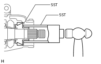
Using SST and a hammer, install the roller bearing (outer).
09316-60011
09316-00011
09316-00021
INSTALL FRONT DRIVE PINION REAR TAPERED ROLLER BEARING (INNER)
Install the roller bearing (inner).
INSTALL FRONT DIFFERENTIAL DRIVE PINION OIL SLINGER
INSTALL FRONT DIFFERENTIAL CARRIER OIL SEAL
INSTALL FRONT DIFFERENTIAL DUST DEFLECTOR
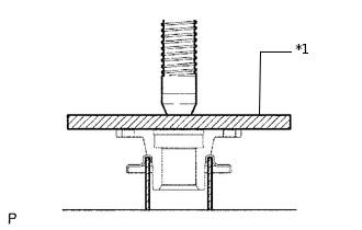
*1
Steel Plate
Using a steel plate and press, press in a new dust deflector.
Note:Do not damage the dust deflector.
INSTALL FRONT DRIVE PINION COMPANION FLANGE SUB-ASSEMBLY
INSTALL DIFFERENTIAL SIDE BEARING RETAINER
Remove any old FIPG material from the side bearing retainer.
Note:Do not drop oil on the contact surfaces of the differential carrier and side bearing retainer.
Wipe off any residual FIPG material on the contact surface using gasoline or alcohol.
-
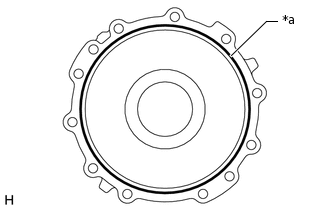
*a
Seal Packing
Apply seal packing to the side bearing retainer as shown in the illustration.
Seal packing
Toyota Genuine Seal Packing 1281, Three Bond 1281 or equivalent
Tip:Install the side bearing retainer within 10 minutes of applying seal packing.
Install the side bearing retainer with the 10 bolts.
75 N*m
765 kgf*cm
55 ft.*lbf
INSPECT TOTAL PRELOAD
Using a torque wrench, measure the preload with the teeth of the drive pinion and ring gear in contact.
Standard Total Preload (at Starting)
Item
Specified Condition
New bearing
1.3 to 2.9 N*m (14 to 29 kgf*cm, 12 to 25 in.*lbf)
Used bearing
0.81 to 1.76 N*m (9 to 17 kgf*cm, 8 to 15 in.*lbf)
If necessary, disassemble and inspect the differential.
INSPECT DIFFERENTIAL RING GEAR BACKLASH
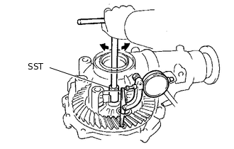
Using SST and a dial indicator, measure the ring gear backlash.
09564-32011
Standard backlash
0.11 to 0.21 mm (0.0043 to 0.00826 in.)
If the backlash is not within the specification, adjust the side bearing preload.
INSPECT FRONT DRIVE PINION COMPANION FLANGE SUB-ASSEMBLY
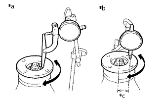
*a
Vertical runout
*b
Lateral runout
*c
30 mm
Using a dial indicator, measure the runout of the companion flange vertically and laterally.
Distance from center to runout measurement point
30 mm (1.18 in.)
Maximum Runout
Item
Specified Condition
Vertical runout
0.10 mm (0.00394 in.)
Lateral runout
0.10 mm (0.00394 in.)
If the runout is more than the maximum, replace the companion flange.
STAKE FRONT DRIVE PINION COMPANION FLANGE NUT
INSTALL DIFFERENTIAL SIDE GEAR SHAFT OIL SEAL
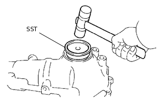
Coat the lip of a new oil seal with MP grease.
Using SST and a plastic-faced hammer, tap in the oil seal until its surface is flush with the differential carrier end.
09608-32010
Standard oil seal depth
-0.45 to 0.45 mm (-0.0177 to 0.0177 in.)
INSTALL FRONT DIFFERENTIAL SIDE BEARING RETAINER DEFLECTOR
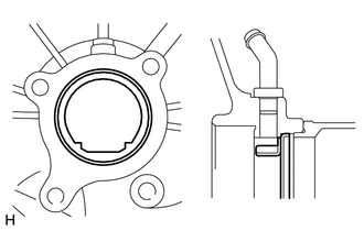
Using a brass bar and hammer, tap in the side bearing retainer deflector.
Note:Install the side bearing retainer deflector so that it is facing in the correct direction.
INSTALL FRONT DIFFERENTIAL TUBE ASSEMBLY
Remove any old FIPG material from the contact surfaces of the differential and clutch case.
Note:Do not drop oil on the contact surfaces of the differential and clutch case.
Wipe off any residual FIPG material on the contact surface using gasoline or alcohol.
-
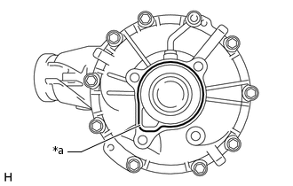
*a
Seal Packing
Apply seal packing to the differential as shown in the illustration.
Seal packing
Toyota Genuine Seal Packing 1281, Three Bond 1281 or equivalent
Tip:Install the differential tube within 10 minutes of applying seal packing.
Install the differential tube to the differential.
Clean the threads of the 4 bolts and retainer bolt holes with toluene or trichloroethylene.
Apply adhesive to 2 or 3 threads at the tip of each bolt.
Adhesive
Toyota Genuine Adhesive 1324, Three Bond 1324 or equivalent
Using an E14 "TORX" socket wrench, install the 4 bolts.
110 N*m
1122 kgf*cm
81 ft.*lbf