LIGHTING SYSTEM Interior Light Circuit
| DTC Code | DTC Name |
|---|---|
| Interior Light Circuit |
DESCRIPTION
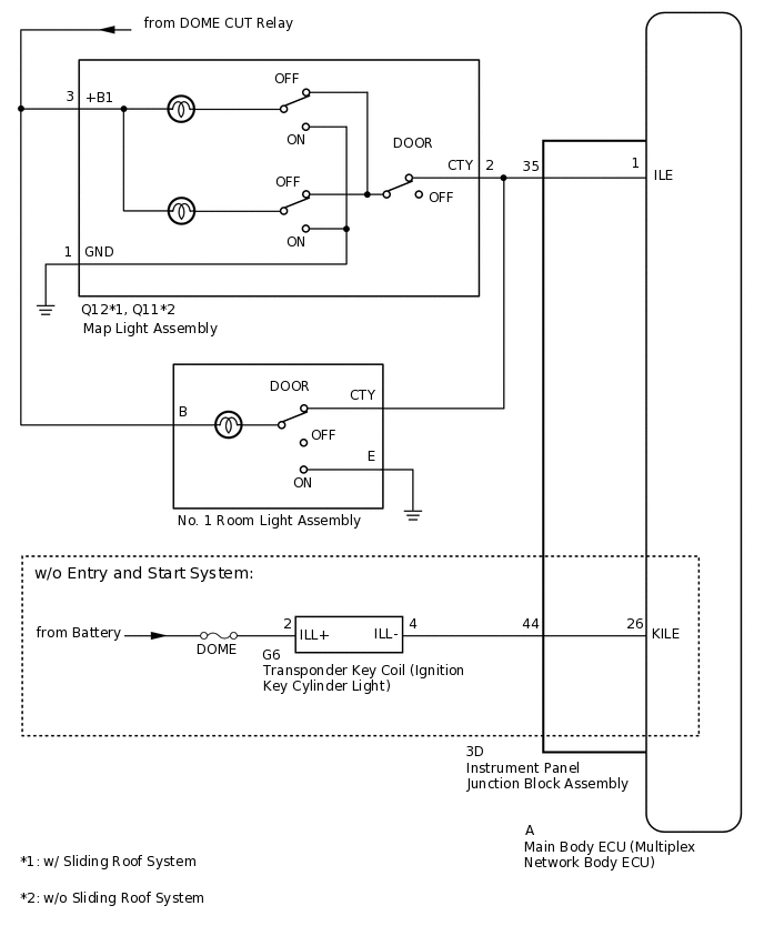
The main body ECU (multiplex network body ECU) controls the ignition key cylinder light (w/o Entry and Start System), map light and No. 1 room light.
WIRING DIAGRAM
CAUTION / NOTICE / HINT
Inspect the fuses and bulbs for circuits related to this system before performing the following inspection procedure.
When replacing the main body ECU (multiplex network body ECU), make sure to replace it with a new one.
PROCEDURE
PERFORM ACTIVE TEST USING GTS (MAP LIGHT, NO. 1 ROOM LIGHT AND IGNITION KEY CYLINDER LIGHT)
Using the GTS, perform the Active Test.
Body Electrical > Main Body > Active Test
Tester Display
Measurement Item
Control Range
Diagnostic Note
Illuminated Entry System
Map light, ignition key cylinder light (w/o Entry and Start System) and No. 1 room light
ON or OFF
Turn the map light switch and No. 1 room light switch to the DOOR position.
Body Electrical > Main Body > Active Test
Tester Display
Illuminated Entry System
Result
Result
Proceed to
Map light assembly, No. 1 room light assembly and ignition key cylinder light comes on
A
Map light assembly and No. 1 room light assembly does not comes on
B
Map light assembly or No. 1 room light assembly does not comes on
C
Ignition key cylinder light does not comes on (w/o Entry and Start System)
D
D INSPECT TRANSPONDER KEY COIL (IGNITION KEY CYLINDER LIGHT)Click here
INSPECT MAP LIGHT ASSEMBLY
Remove the map light assembly.
Inspect the map light assembly.
Result
Proceed to
OK
NG
CHECK HARNESS AND CONNECTOR (MAP LIGHT ASSEMBLY - BATTERY AND BODY GROUND)
-
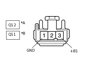
*A
w/ Sliding Roof System
*B
w/o Sliding Roof System
Disconnect the map light assembly connector.
Measure the voltage according to the value(s) in the table below.
Standard Voltage
w/ Sliding Roof System
Tester Connection
Condition
Specified Condition
Q12-3 (+B1) - Body ground
Battery saving control (interior light auto cut function) not operating
11 to 14 V
w/o Sliding Roof System
Tester Connection
Condition
Specified Condition
Q11-3 (+B1) - Body ground
Battery saving control (interior light auto cut function) not operating
11 to 14 V
Measure the resistance according to the value(s) in the table below.
Standard Resistance
w/ Sliding Roof System
Tester Connection
Condition
Specified Condition
Q12-1 (GND) - Body ground
Always
Below 1 Ω
w/o Sliding Roof System
Tester Connection
Condition
Specified Condition
Q11-1 (GND) - Body ground
Always
Below 1 Ω
Result
Proceed to
OK
NG
NG REPAIR OR REPLACE HARNESS OR CONNECTOR
-
CHECK HARNESS AND CONNECTOR (MAP LIGHT ASSEMBLY - INSTRUMENT PANEL JUNCTION BLOCK ASSEMBLY)
Disconnect the Q12*1 or Q11*2 map light assembly connector.
*1: w/ Sliding Roof System
*2: w/o Sliding Roof System
Disconnect the 3D instrument panel junction block assembly connector.
Measure the resistance according to the value(s) in the table below.
Standard Resistance
w/ Sliding Roof System
Tester Connection
Condition
Specified Condition
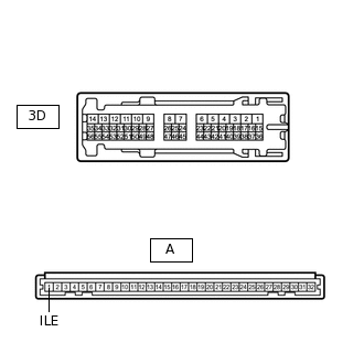
Q12-2 (CTY) - 3D-35
Always
Below 1 Ω
Q12-2 (CTY) - Body ground
Always
10 kΩ or higher
w/o Sliding Roof System
Tester Connection
Condition
Specified Condition
Q11-2 (CTY) - 3D-35
Always
Below 1 Ω
Q11-2 (CTY) - Body ground
Always
10 kΩ or higher
Result
Proceed to
OK
NG
INSPECT INSTRUMENT PANEL JUNCTION BLOCK ASSEMBLY
-
Remove the instrument panel junction block assembly.
for LHD:
for RHD:
Remove the main body ECU (multiplex network body ECU) from the instrument panel junction block assembly.
for LHD:
for RHD:
Measure the resistance according to the value(s) in the table below.
Standard Resistance
Tester Connection
Condition
Specified Condition
A-1 (ILE) - 3D-35
Always
Below 1 Ω
Result
Proceed to
OK
NG
-
INSPECT TRANSPONDER KEY COIL (IGNITION KEY CYLINDER LIGHT)
Remove the transponder key coil (ignition key cylinder light).
Inspect the transponder key coil (ignition key cylinder light).
Result
Proceed to
OK
NG
CHECK HARNESS AND CONNECTOR (TRANSPONDER KEY COIL [IGNITION KEY CYLINDER LIGHT] - INSTRUMENT PANEL JUNCTION BLOCK ASSEMBLY AND BATTERY)
Disconnect the G6 transponder key coil (ignition key cylinder light) connector.
Disconnect the 3D instrument panel junction block assembly connector.
Measure the voltage according to the value(s) in the table below.
Standard Voltage
Tester Connection
Condition
Specified Condition
G6-2 (ILL+) - Body ground
Always
11 to 14 V
Measure the resistance according to the value(s) in the table below.
Standard Resistance
Tester Connection
Condition
Specified Condition
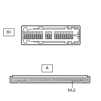
G6-4 (ILL-) - 3D-44
Always
Below 1 Ω
G6-4 (ILL-) - Body ground
Always
Below 1 Ω
Result
Proceed to
OK
NG
NG REPAIR OR REPLACE HARNESS OR CONNECTOR
INSPECT INSTRUMENT PANEL JUNCTION BLOCK ASSEMBLY
-
Remove the instrument panel junction block assembly.
for LHD:
for RHD:
Remove the main body ECU (multiplex network body ECU) from the instrument panel junction block assembly.
for LHD:
for RHD:
Measure the resistance according to the value(s) in the table below.
Standard Resistance
Tester Connection
Condition
Specified Condition
A-26 (KILE) - 3D-44
Always
Below 1 Ω
Result
Proceed to
OK
NG
-