FRONT CRANKSHAFT OIL SEAL(w/o Glow Plug Controller) INSTALLATION
PROCEDURE
INSTALL TIMING CHAIN COVER OIL SEAL
Apply MP grease to a new timing chain cover oil seal lip.
Note:Keep the lip free from foreign matter.
-
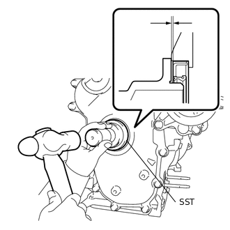
Using SST and a hammer, tap in the new timing chain cover oil seal until its surface is flush with the timing chain cover sub-assembly.
09223-22010
Oil Seal Tap in Depth
-0.6 to 0 mm (-0.0236 to 0 in.)
Note:Do not tap in the timing chain cover oil seal at an angle.
Wipe off excess grease from the crankshaft.
INSTALL CRANKSHAFT DAMPER SUB-ASSEMBLY
Align the key with the key groove of the crankshaft damper sub-assembly, and install the crankshaft damper sub-assembly to the crankshaft.
-

*a
Hold
*b
Turn
Using SST, hold the crankshaft damper sub-assembly.
09213-58014
09330-00021
Tighten the bolt to the specified torque.
210 N*m
2141 kgf*cm
155 ft.*lbf
INSTALL ENGINE MOUNTING INSULATOR SUB-ASSEMBLY RH
Set the engine mounting insulator RH sub-assembly onto the vehicle and engine mouthing bracket RH.
-

Install the engine mounting insulator sub-assembly RH with the 3 bolts and 3 nuts.
Bolt
95 N*m
969 kgf*cm
70 ft.*lbf
Nut (A)
95 N*m
969 kgf*cm
70 ft.*lbf
Nut (B)
52 N*m
530 kgf*cm
38 ft.*lbf
Connect the cooler pipe clamp to the engine mounting insulator sub-assembly RH.
Install the cooler pipe clamp bracket with the bolt.
9.8 N*m
100 kgf*cm
87 in.*lbf
INSTALL RADIATOR RESERVE TANK ASSEMBLY
Install the radiator reserve tank assembly with the 2 bolts.
5.0 N*m
51 kgf*cm
44 in.*lbf
INSTALL FRONT EXHAUST PIPE ASSEMBLY
-

Using a vernier caliper, measure the free length of the compression springs.
Minimum
41.5 mm (1.63 in.)
If the free length is less than the minimum, replace the compression spring.
-

*1
No. 2 Exhaust Manifold Converter Sub-assembly
*2
Gasket
*a
Wooden Block
Using a plastic hammer and wooden block, tap in a new gasket until its surface is flush with the No. 2 exhaust manifold converter sub-assembly.
Note:Be careful with the installation direction of the gasket.
Do not reuse the gasket.
Do not damage the gasket.
Do not push in the gaskets by using the front exhaust pipe sub-assembly when connecting it.
-
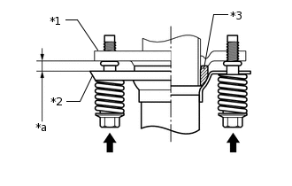
*1
No. 2 Exhaust Manifold Converter Sub-assembly
*2
Front Exhaust Pipe Assembly
*3
Gasket
*a
Space Between Flanges: 8.5 mm (0.335 in.)
Install the front exhaust pipe assembly to the No. 2 exhaust manifold converter sub-assembly with the 2 bolts and 2 compression springs.
43 N*m
438 kgf*cm
32 ft.*lbf
Tip:After installation, check that the space between the flanges of the No. 2 exhaust manifold converter sub-assembly and front exhaust pipe assembly are consistent front-to-rear and left-to-right.
-
INSTALL FRONT ENGINE MOUNTING BRACKET LOWER REINFORCEMENT (w/ Reinforcement)
INSTALL FRONT SUSPENSION MEMBER REINFORCEMENT RH
INSTALL V-RIBBED BELT
INSPECT FOR OIL LEAK
INSTALL NO. 1 ENGINE COVER (w/ No. 1 Engine Cover)
INSTALL REAR ENGINE UNDER COVER RH
INSTALL NO. 1 ENGINE UNDER COVER (for Half Cover Type)
INSTALL NO. 1 ENGINE UNDER COVER (for Full Cover Type)
INSTALL FRONT WHEEL RH
103 N*m
1050 kgf*cm
76 ft.*lbf