METER / GAUGE SYSTEM Engine Coolant Temperature Gauge Malfunction
DESCRIPTION
In this circuit, the meter CPU receives engine coolant temperature signals from the ECM. The meter CPU displays engine coolant temperature that is calculated based on the data received from the ECM.
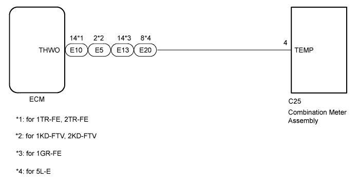
WIRING DIAGRAM
INSPECTION PROCEDURE
PROCEDURE
-
CHECK FOR DTC
-
*1: for 1KD-FTV, 2KD-FTV, 5L-E
-
*2: for 1TR-FE, 2TR-FE, 1GR-FE
-
Check for DTCs of the ECD system*1 or SFI system*2.
Result Result Proceed to DTC is not output A DTC is output (for 1KD-FTV, 2KD-FTV, 5L-E) B DTC is output (for 1TR-FE, 2TR-FE, 1GR-FE) C
B 
GO TO ECD SYSTEM
C
GO TO SFI SYSTEM
A 
-
-
CHECK HARNESS AND CONNECTOR (COMBINATION METER ASSEMBLY - ECM)
-
*1: for 1KD-FTV, 2KD-FTV
-
*2: for 2TR-FE
-
*3: for 1GR-FE
-
*4: for 5L-E
-
Disconnect the C25 combination meter assembly connector.
-
Disconnect the E5*1 or E10*2 or E13*3 or E20*4 ECM connector.
-
Measure the resistance of the wire harness side connectors.
Standard Resistance for 1KD-FTV, 2KD-FTV Tester Connection Condition Specified Condition C25-4 (TEMP) - E5-2 (THWO) Always Below 1 Ω C25-4 (TEMP) or E5-2 (THWO) - Body ground Always 10 kΩ or higher for 1TR-FE, 2TR-FE Tester Connection Condition Specified Condition C25-4 (TEMP) - E10-14 (THWO) Always Below 1 Ω C25-4 (TEMP) or E10-14 (THWO) - Body ground Always 10 kΩ or higher for 1GR-FE Tester Connection Condition Specified Condition C25-4 (TEMP) - E13-14 (THWO) Always Below 1 Ω C25-4 (TEMP) or E13-14 (THWO) - Body ground Always 10 kΩ or higher for 5L-E Tester Connection Condition Specified Condition C25-4 (TEMP) - E20-8 (THWO) Always Below 1 Ω C25-4 (TEMP) or E20-8 (THWO) - Body ground Always 10 kΩ or higher
NG
REPAIR OR REPLACE HARNESS OR CONNECTOR
OK
-
-
REPLACE COMBINATION METER ASSEMBLY
-
Replace the combination meter assembly with a new or normally functioning one Click here.
OK The operation of the engine coolant temperature gauge returns to normal.
NG
REPLACE ECM
OK 
END (COMBINATION METER ASSEMBLY IS DEFECTIVE)
-