RADIO RECEIVER REMOVAL
PROCEDURE
-
PRECAUTION
Note
After turning the power switch off, waiting time may be required before disconnecting the cable from the negative (-) auxiliary battery terminal. Therefore, make sure to read the disconnecting the cable from the negative (-) auxiliary battery terminal notices before proceeding with work Click here.
-
REMOVE DECK BOARD ASSEMBLY
-
REMOVE NO. 1 DECK BOARD
-
REMOVE NO. 2 DECK BOARD
-
REMOVE REAR DECK FLOOR BOX
-
REMOVE DECK FLOOR BOX RH
-
DISCONNECT CABLE FROM NEGATIVE AUXILIARY BATTERY TERMINAL
Note
When disconnecting the cable, some systems need to be initialized after the cable is reconnected Click here.
-
REMOVE INTEGRATION CONTROL AND PANEL
-
REMOVE INSTRUMENT PANEL BOX ASSEMBLY
-
REMOVE CENTER INSTRUMENT PANEL REGISTER ASSEMBLY
-
REMOVE RADIO AND DISPLAY RECEIVER ASSEMBLY WITH BRACKET
-
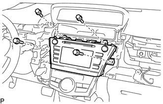
Remove the 4 bolts.
-
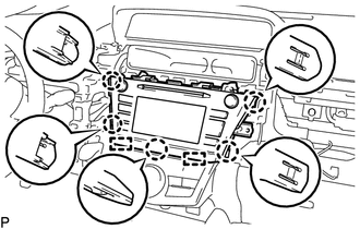
Disengage the 5 claws and 2 guides.
-
Disconnect each connector and remove the radio and display receiver assembly with bracket.
-
-
REMOVE NO. 1 NAVIGATION WIRE (w/ Navigation System)
-
REMOVE ANTENNA CORD SUB-ASSEMBLY (w/ Navigation System)
-
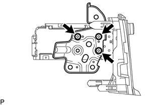
REMOVE NO. 1 RADIO RECEIVER BRACKET
-
w/o Navigation System:
-
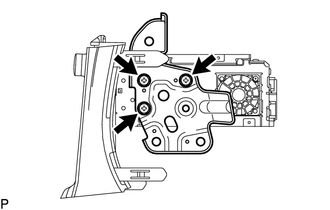
Remove the 3 screws and No. 1 radio receiver bracket.
-
-
w/ Navigation System:
-
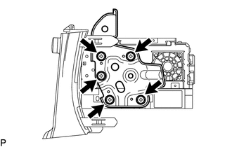
Remove the 5 screws and No. 1 radio receiver bracket.
-
-
-
REMOVE NO. 2 RADIO RECEIVER BRACKET
-
w/o Navigation System:
-
Remove the 3 screws and No. 2 radio receiver bracket.
-
-
w/ Navigation System:
-
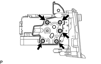
Remove the 5 screws and No. 2 radio receiver bracket.
-
-
-
REMOVE NAVIGATION ECU (w/ Navigation System)
-
REMOVE RADIO AND DISPLAY RECEIVER ASSEMBLY