ROOF HEADLINING INSTALLATION

CAUTION / NOTICE / HINT
Tech Tips
-
Use the same procedure for RHD and LHD vehicles.
-
The procedure listed below is for LHD vehicles.
-
Use the same procedure for the RH and LH sides.
-
The procedure listed below is for the LH side.
-
A bolt without a torque specification is shown in the standard bolt chart.
PROCEDURE
-
INSTALL OUTSIDE REAR DOOR SCUFF PLATE LH
-
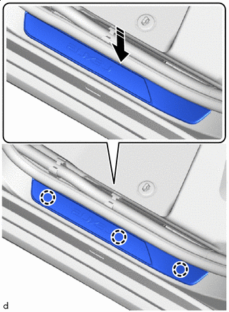

Install in this Direction Attach the claw to install the outside rear door scuff plate LH in the direction indicated by the arrow shown in the illustration.
-
Remove the protective tape.
-
-
INSTALL OUTSIDE REAR DOOR SCUFF PLATE RH
Tech Tips
Use the same procedure described for the LH side.
-
INSTALL OUTSIDE FRONT DOOR SCUFF PLATE LH
-
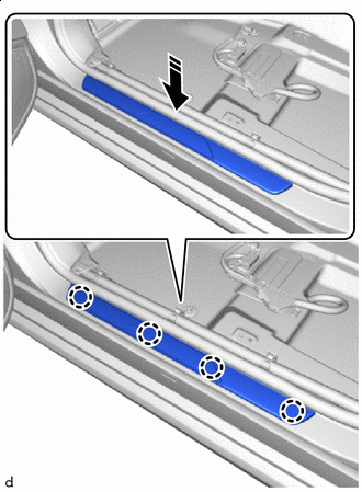
Install in this Direction Attach the claw to install the outside front door scuff plate LH in the direction indicated by the arrow shown in the illustration.
-
Remove the protective tape.
-
-
INSTALL OUTSIDE FRONT DOOR SCUFF PLATE RH
Tech Tips
Use the same procedure described for the LH side.
-
INSTALL ROOF HEADLINING ASSEMBLY
-
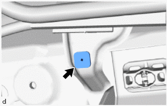
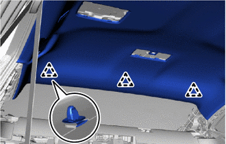
Install a new grommet to the vehicle.
Tech Tips
Use the same procedure for the opposite side.
-
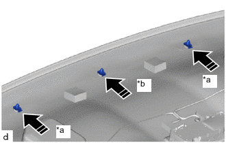
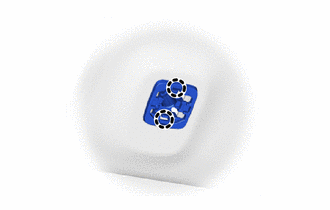
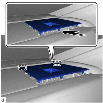
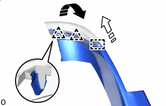
*a Clip (White) *b Clip (Black) Install in this Direction Install the 3 clips to the roof headlining assembly.
-
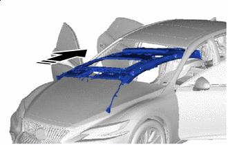
Install in this Direction Tilt the roof headlining assembly and insert it from the front of the vehicle.
Note
-
Installation of the roof headlining assembly must be performed by multiple people to prevent deformation of the roof headlining assembly.
-
Check that the corners of the roof headlining assembly are free of bending, twisting and other deformation and that none of the mounted parts are falling off.
-
Do not damage the roof headlining assembly and body interior.
-
-
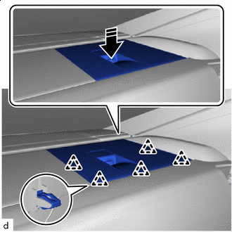
Attach the clip.
-
for Sliding Roof:
-
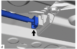
Insert the guide.
-
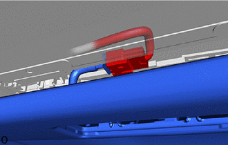
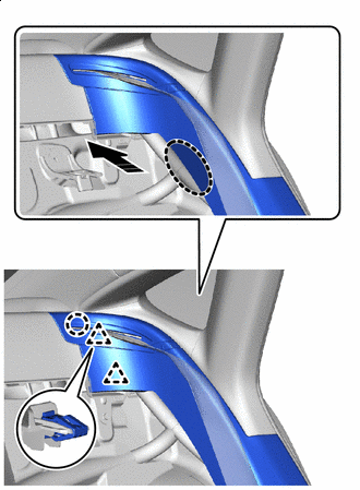
Push the roof headlining assembly up in the direction indicated by the arrow shown in the illustration and attach the hook, fastener and claw.
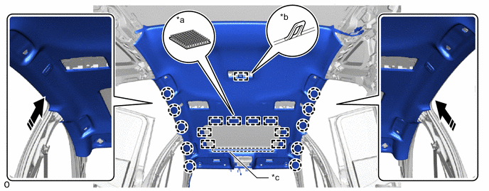
*a Fastener *b Hook *c Guide - - Install in this Direction - -
-
-
for Panoramic Moon Roof:
-
Insert the guide.
-
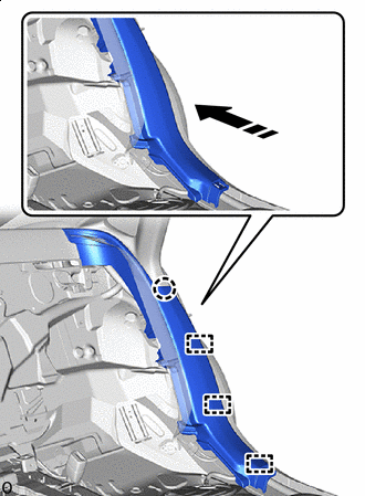
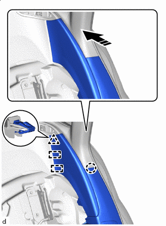
Push the roof headlining assembly up in the direction indicated by the arrow shown in the illustration and attach the fastener and claw.
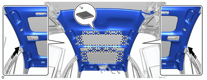
*a Fastener *b Guide Install in this Direction - -
-
-
for Panoramic Moon Roof:
-
Connect the connector.
-
-
w/ Rear Cooler:
-
Install the screw.
Tech Tips
Use the same procedure for the opposite side.
-
-
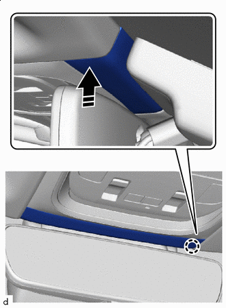
Connect the connector.
-
Attach the claw to install the base of the visor holder LH as shown in the illustration.
Tech Tips
Use the same procedure for the opposite side.
-
Front pillar LH side:
-
Remove the protective cover installed to the front pillar LH.
-
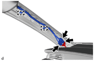
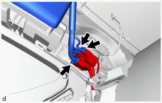
Attach the clamp and connect the 3 connectors.
-
Install the protective cover to the front pillar LH.
-
-
Rear pillar RH side:
-
Connect the 3 connectors.
-
-
-
INSTALL WINDSHIELD GLASS
-
INSTALL MAP LIGHT ASSEMBLY
-
INSTALL FRONT ROOF TOP GARNISH
-
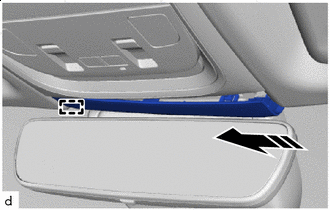
Install in this Direction Insert the guide in the direction indicated by the arrow shown in the illustration.
-
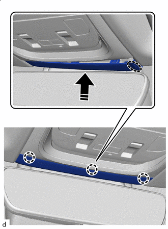
Install in this Direction Push in the direction indicated by the arrow shown in the illustration to attach the claw.
-
Install in this Direction Attach the claw in the direction indicated by the arrow shown in the illustration to attach the claw to install the front roof top garnish.
-
-
INSTALL VANITY LIGHT ASSEMBLY
-
INSTALL VISOR HOLDER LH
-
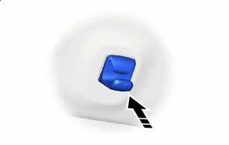
Install in this Direction Push in the end of the visor holder LH to install the visor holder LH.
-
-
INSTALL VISOR ASSEMBLY LH
-
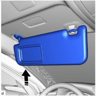
Install in this Direction Set the visor assembly LH into place by aligning it upward with the connector and screw fastening hole.
Note
-
When setting the part into place, move it straight upward so as not to damage the connector.
-
Hold the visor assembly with one hand so that it does not drop.
-
-
Connect the visor assembly LH to the visor holder LH to set it into place.
-
Install the visor assembly RH with the 2 screws.
-
-
INSTALL VISOR BRACKET COVER LH
-
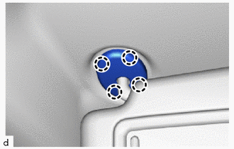
Attach the claw to install the visor bracket cover LH.
-
-
INSTALL VISOR HOLDER RH
Tech Tips
Use the same procedure described for the LH side.
-
INSTALL VISOR ASSEMBLY RH
Tech Tips
Use the same procedure described for the LH side.
-
INSTALL VISOR BRACKET COVER RH
Tech Tips
Use the same procedure described for the LH side.
-
INSTALL COAT HOOK (w/o Rear Cooler)
-
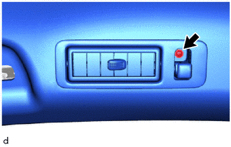
Install in this Direction Attach the claw to install the coat hook.
-
Install the screw.
-
-
INSTALL VANITY MIRROR ASSEMBLY
-
INSTALL SPOT LIGHT ASSEMBLY (for Sliding roof)
-
INSTALL SPOT LIGHT ASSEMBLY LH (for Panoramic Moon Roof)
-
INSTALL SPOT LIGHT ASSEMBLY RH (for Panoramic Moon Roof)
Tech Tips
Use the same procedure described for the LH side.
-
INSTALL ASSIST GRIP SUB-ASSEMBLY
Tech Tips
Use the same procedure for the other assist grips.
-
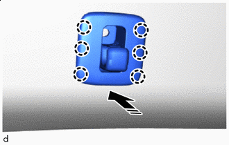
Install the 2 clips to the assist grip sub-assembly.
-
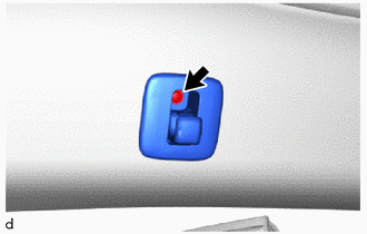
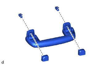
Temporarily install the 2 assist grip covers to the assist grip sub-assembly as shown in the illustration.
-
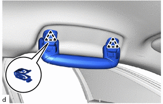
Attach the clip to install the assist grip sub-assembly.
-
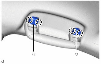
*1 Assist Grip Cover LH *2 Assist Grip Cover RH Attach the claw to install the assist grip cover LH and assist grip cover RH.
Note
Check that the 2 clips are securely attached.
-
-
INSTALL INNER ROOF SIDE GARNISH ASSEMBLY LH
-
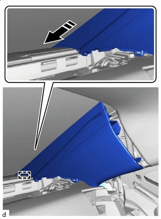
Install in this Direction Insert the guide in the direction indicated by the arrow shown in the illustration.
-
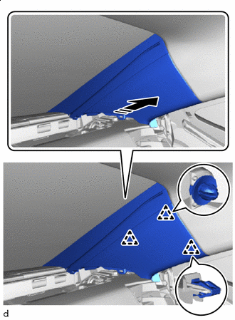
Install in this Direction Push in the direction indicated by the arrow shown in the illustration to attach the clip to install the inner roof side garnish assembly LH.
-
-
INSTALL INNER ROOF SIDE GARNISH ASSEMBLY RH
Tech Tips
Use the same procedure described for the LH side.
-
INSTALL PACKAGE TRAY TRIM SIDE COVER LH
-
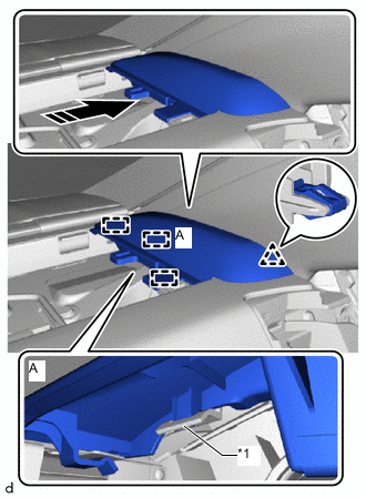
*1 Inner Roof Side Garnish Assembly LH Install in this Direction Attach the clamp and clip in the direction indicated by the arrow shown in the illustration to install the package tray trim side cover LH.
Note
When attaching clamp A, push down on the roof side inner garnish assembly LH side.
-
-
INSTALL PACKAGE TRAY TRIM SIDE COVER RH
Tech Tips
Use the same procedure described for the LH side.
-
INSTALL PACKAGE TRAY TRIM GARNISH LH
-
Install in this Direction Insert the guide in the direction indicated by the arrow shown in the illustration.
-
Install in this Direction Push in the direction indicated by the arrow shown in the illustration to install the package tray trim garnish LH.
-
Remove the protective tape.
-
-
INSTALL PACKAGE TRAY TRIM GARNISH RH
Tech Tips
Use the same procedure described for the LH side.
-
INSTALL ROOF SIDE RAIL GARNISH ASSEMBLY LH
-
Install in this Direction Attach the clip in the direction indicated by the arrow shown in the illustration.
-
Install in this Direction Attach the clip to install the roof side rail garnish assembly LH in the direction indicated by the arrow shown in the illustration.
-
-
INSTALL ROOF SIDE RAIL GARNISH ASSEMBLY RH
Tech Tips
Use the same procedure described for the LH side.
-
INSTALL REAR SEAT SIDE GARNISH LH
-
for Fixed Seat Type:
-
Install in this Direction (1) 
Install in this Direction (2) Insert the guide in the direction (1) indicated by the arrow shown in the illustration.
-
Attach the clip in the direction (2) indicated by the arrow shown in the illustration to install the seat belt guide to the rear seat side garnish LH.
-
Install in this Direction Attach the clip and claw in the direction indicated by the arrow shown in the illustration.
-
Install in this Direction Push in the direction indicated by the arrow shown in the illustration to attach the clamp and claw to install the rear seat side garnish LH.
-
-
for Power Seat:
-
Install in this Direction Insert the guide and attach the clip and claw in the direction indicated by the arrow shown in the illustration.
-
Install in this Direction Push in the direction indicated by the arrow shown in the illustration to attach the clamp to install the rear seat side garnish LH.
-
-
-
INSTALL REAR SEAT SIDE GARNISH RH
Tech Tips
Use the same procedure described for the LH side.
-
INSTALL UPPER CENTER PILLAR GARNISH LH
-
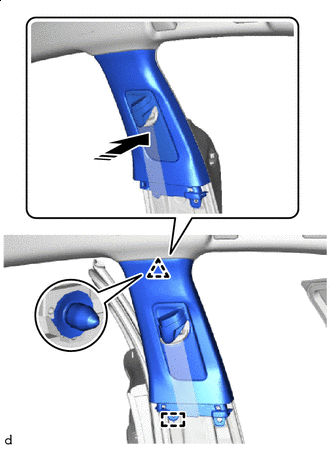
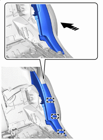
Install in this Direction Align the hook, attach the clip to install the upper center pillar garnish LH in the direction indicated by the arrow shown in the illustration.
-
Install the 2 clips.
-
-
INSTALL UPPER CENTER PILLAR GARNISH RH
Tech Tips
Use the same procedure described for the LH side.
-
INSTALL LOWER CENTER PILLAR GARNISH LH
-
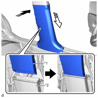
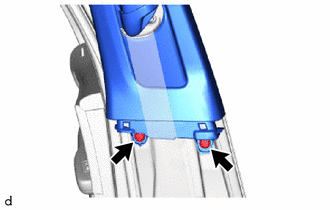
*1 Rear Cooler Air Duct Adapter LH *2 No. 2 Floor Heater Air Duct LH Install in this Direction (1) Install in this Direction (2) Align the rear cooler air duct adapter LH of the lower center pillar garnish LH with the position of the No. 2 floor heater air duct RH in the installation direction (1) shown in the illustration.
-
Insert the rear cooler air duct adapter LH in the installation direction (2) shown in the illustration.
-
Install in this Direction Push in the direction indicated by the arrow shown in the illustration to attach the claw and clip to install the lower center pillar garnish RH.
-
-
INSTALL LOWER CENTER PILLAR GARNISH RH
Tech Tips
Use the same procedure described for the LH side.
-
INSTALL FRONT PILLAR GARNISH LH
-
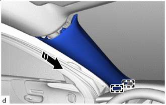
Peel off the adhesive tape and remove the protective cover.
-
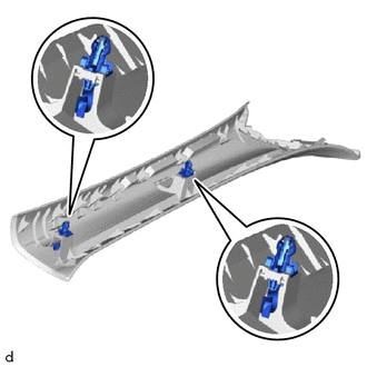
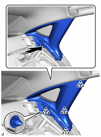
Install the 2 front pillar garnish clips to the front pillar garnish LH.
Note
-
If there is extreme damage to the front pillar garnish clip, replace it with a new one.
-
Make sure that the position and direction of the front pillar garnish clip is correct when installing.
-
-
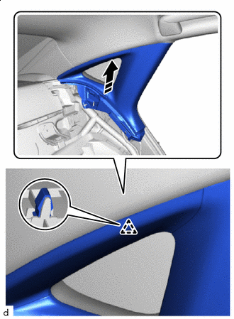
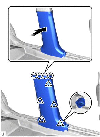
Install in this Direction Insert the guide in the direction indicated by the arrow shown in the illustration.
-
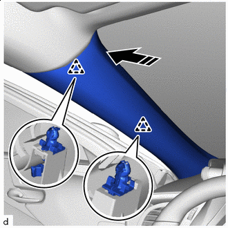
Install in this Direction Push in the direction indicated by the arrow shown in the illustration to attach the clip to install the front pillar garnish LH.
-
-
INSTALL FRONT PILLAR GARNISH RH
Tech Tips
Use the same procedure described for the LH side.
-
INSTALL REAR DOOR SCUFF PLATE LH
-
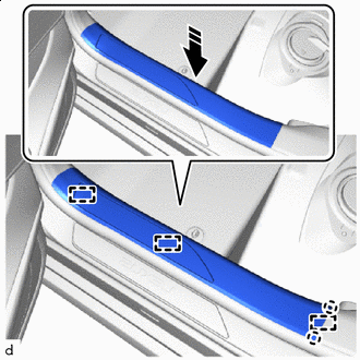
Install in this Direction Attach the claw and align the guide in the direction indicated by the arrow shown in the illustration.
-
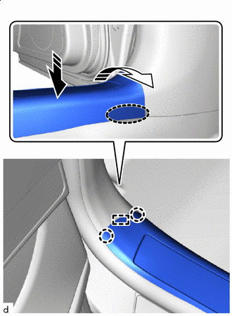

Place hand here Install in this Direction (1) Install in this Direction (2) Push in the installation direction (1) shown in the illustration to attach the claw on the vehicle exterior side and align the guide.
-
Place your hand at the position shown in the illustration and attach the claw while pulling in the installation direction (2) to install the rear door scuff plate LH.
-
-
INSTALL REAR DOOR SCUFF PLATE RH
Tech Tips
Use the same procedure described for the LH side.
-
INSTALL FRONT DOOR SCUFF PLATE LH
-
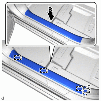
Install in this Direction Attach the claw and align the guide in the direction indicated by the arrow shown in the illustration.
-
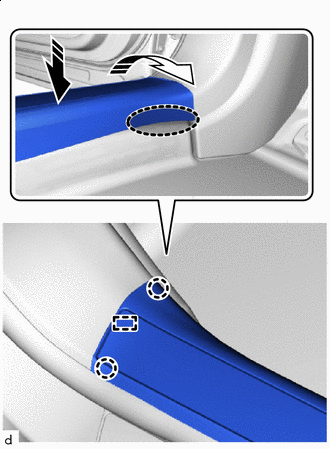
Place hand here Install in this Direction (1) Install in this Direction (2) Push in the installation direction (1) shown in the illustration to attach the claw on the vehicle exterior side and align the guide.
-
Place your hand at the position shown in the illustration and attach the claw while pulling in the installation direction (2) to install the front door scuff plate LH.
-
-
INSTALL FRONT DOOR SCUFF PLATE RH
Tech Tips
Use the same procedure described for the LH side.
-
INSTALL REAR SEATBACK ASSEMBLY LH (for Power Seat)
-
INSTALL REAR SEATBACK ASSEMBLY RH (for Power Seat)
Tech Tips
Use the same procedure described for the LH side.
-
INSTALL REAR SEAT CUSHION LOCK HOOK (for Power Seat)
-
INSTALL REAR SEAT CUSHION ASSEMBLY LH (for Power Seat)
-
INSTALL REAR SEAT CUSHION ASSEMBLY RH (for Power Seat)
Tech Tips
Use the same procedure described for the LH side.
-
INSTALL REAR SEATBACK HOLDER (for Fixed Seat Type)
-
INSTALL REAR SEAT CUSHION LOCK HOOK (for Fixed Seat Type)
-
INSTALL REAR SEATBACK ASSEMBLY (for Fixed Seat Type)
-
INSTALL NO. 1 SEAT ARMREST CAP (for Fixed Seat Type)
-
INSTALL REAR SEAT CUSHION ASSEMBLY (for Fixed Seat Type)
-
INSTALL FRONT SEAT ASSEMBLY LH
-
INSTALL FRONT SEAT ASSEMBLY RH
Tech Tips
Use the same procedure described for the LH side.
-
CHECK SRS WARNING LIGHT