VALVE BODY ASSEMBLY(for V35A-FTS) INSTALLATION
PROCEDURE
-
INSTALL WIRE HARNESS CLAMP
-
Install the wire harness clamp to the transmission valve body assembly with the bolt.
- Torque:
- 10 N*m { 102 kgf*cm, 7 ft.*lbf }
-
-
INSTALL TRANSMISSION VALVE BODY ASSEMBLY
-

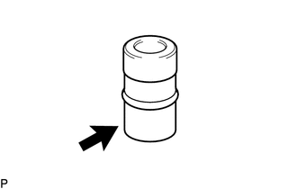
Coat the 2 new O-rings with ATF and install them to the oil pump suction pipe and oil pump delivery pipe.
-
Coat the 3 new brake drum gaskets with ATF.
-
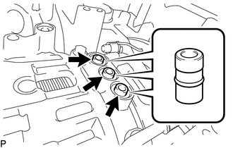
Install the 3 brake drum gaskets to the automatic transmission case as shown in the illustration.
-
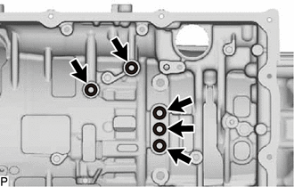
Coat the 5 new gaskets with ATF and install them to the automatic transmission case.
-
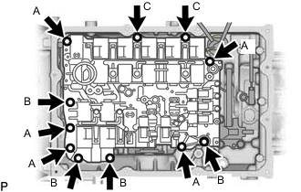
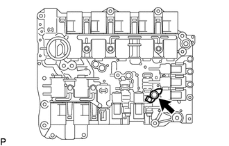
Install the transmission valve body assembly to the automatic transmission case with the 11 bolts.
- Torque:
- 11 N*m { 112 kgf*cm, 8 ft.*lbf }
Bolt Length Bolt A 31 mm (1.22 in.) Bolt B 24 mm (0.945 in.) Bolt C 17 mm (0.669 in.) Note
Take care that the transmission wire does not become trapped.
-
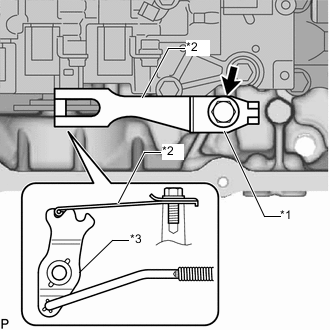
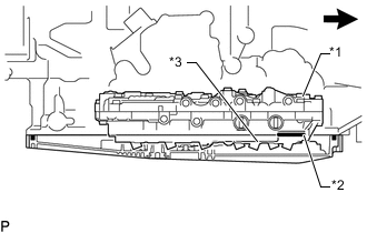
*1 Manual Detent Spring Cover *2 Manual Detent Spring Sub-assembly *3 Manual Valve Lever Sub-assembly Install the manual detent spring sub-assembly and manual detent spring cover to the automatic transmission case with the bolt.
- Torque:
- 24.5 N*m { 250 kgf*cm, 18 ft.*lbf }
Note
Make sure that the center of the roller on the manual detent spring sub-assembly is at the center of the manual valve lever sub-assembly.
-
Coat a new O-ring with the ATF and install it to the ATF temperature sensor.
-
*1 Lock Plate *2 ATF Temperature Sensor Connect the ATF temperature sensor to the transmission valve body assembly with the bolt and lock plate.
- Torque:
- 10 N*m { 102 kgf*cm, 7 ft.*lbf }
Note
Ensure that the O-ring is not twisted or pinched.
-
Connect the transmission wire to the wire harness clamp.
-
Connect the 13 solenoid valve connectors.
-
-
INSTALL ACCUMULATOR WITH SOLENOID ASSEMBLY (w/ Stop And Start System)
-
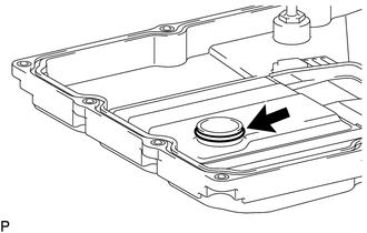
INSTALL NO. 1 TRANSMISSION OIL FILLER TUBE
-
Install the No. 1 transmission oil filler tube to the new automatic transmission oil pan sub-assembly.
- Torque:
- 4.5 N*m { 46 kgf*cm, 40 in.*lbf }
-
-
INSTALL AUTOMATIC TRANSMISSION OIL PAN SUB-ASSEMBLY
-
Coat a new oil strainer O-ring with the ATF.
-
*1 Transmission Valve Body Assembly *2 O-Ring *3 Oil Strainer 
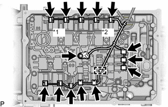
Front of Vehicle Insert the O-ring into the transmission valve body assembly and temporarily install the automatic transmission oil pan sub-assembly with the 12 bolts so that the transmission oil pan gasket touches the automatic transmission case.
Note
Make sure that transmission oil pan gasket seal surface and automatic transmission oil pan sub-assembly contact surface are free of oil and foreign matter.
-
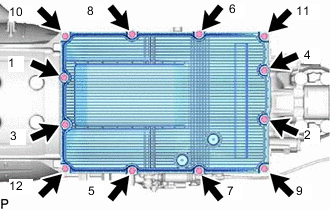
Tighten the 12 bolts in the order shown in the illustration.
- Torque:
- 7.4 N*m { 75 kgf*cm, 65 in.*lbf }
Note
-
Install the transmission oil pan gasket so that there is no slack in the transmission oil pan gasket, and the entire seal surface is level.
-
If not tightened evenly it may result in automatic transmission fluid leakage.
Tech Tips
The tightening order for the bolts are engraved near the oil pan bolt holes.
-
-
INSTALL FRONT EXHAUST PIPE ASSEMBLY
-
ADD AUTOMATIC TRANSMISSION FLUID
-
INSTALL NO. 2 ENGINE UNDER COVER ASSEMBLY
-
INSTALL TRANSMISSION UNDER COVER
-
PERFORM INITIALIZATION
-
CATALYST DETERIORATION CONFIRMATION DRIVING PATTERN
Tech Tips
Proceed to "CONFIRMATION DRIVING PATTERN".
-
w/ Canister Pump Module
-
w/o Canister Pump Module
-