REAR DIFFERENTIAL CARRIER ASSEMBLY DISASSEMBLY

PROCEDURE
-
REMOVE REAR DIFFERENTIAL DYNAMIC DAMPER
-
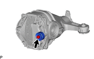
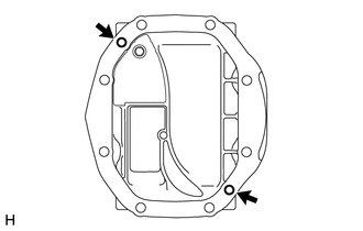
Using a 12 mm hexagon wrench, remove the bolt and rear differential dynamic damper from the rear differential carrier cover.
-
-
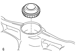
REMOVE REAR DIFFERENTIAL BREATHER PLUG
-
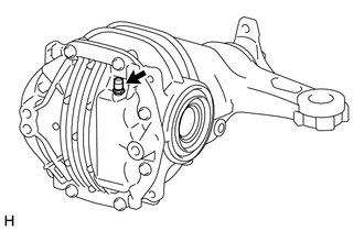
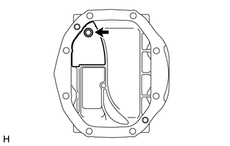
Remove the rear differential breather plug from the rear differential carrier cover.
-
-
REMOVE REAR DIFFERENTIAL CARRIER COVER
-
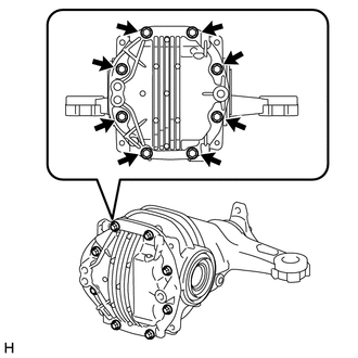
Remove the 8 bolts.
-
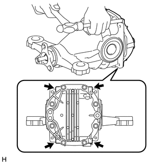
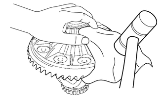
Using a brass bar and hammer, remove the rear differential carrier cover from the rear differential carrier.
Note
-
Place the brass bar onto the corners of the rear differential carrier cover.
-
Do not damage the sealing surface of the rear differential carrier.
-
-
-
REMOVE REAR DIFFERENTIAL CARRIER STRAIGHT PIN
Tech Tips
It is not necessary to remove a rear differential carrier straight pin unless it is being replaced.
-
Remove the 2 rear differential carrier straight pins from the rear differential carrier cover.
-
-
REMOVE REAR DIFFERENTIAL BREATHER PLUG OIL DEFLECTOR
-
Remove the bolt and rear differential breather plug oil deflector from the rear differential carrier cover.
-
-
SECURE REAR DIFFERENTIAL CARRIER ASSEMBLY
-
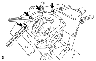
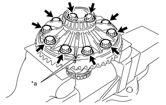
Install the rear differential carrier assembly to an overhaul stand as shown in the illustration.
-
-
INSPECT RUNOUT OF DIFFERENTIAL RING GEAR
-
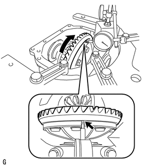
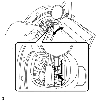
Set a dial indicator perpendicular to the end of the differential ring gear face.
-
Rotate the differential ring gear and measure the runout.
Maximum runout 0.05 mm (0.00197 in.) Tech Tips
If the runout is more than the maximum, remove the differential ring gear and check the runout of the rear differential case sub-assembly.
-
-
INSPECT DIFFERENTIAL RING GEAR BACKLASH
-
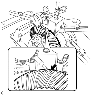
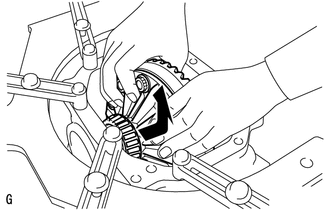
While holding the rear drive pinion companion flange, rotate the differential ring gear and measure the backlash.
Backlash 0.08 to 0.13 mm (0.00315 to 0.00512 in.) Tech Tips
If the backlash is not within the specified range, adjust the backlash or perform repairs as necessary.
-
-
INSPECT TOOTH CONTACT BETWEEN RING GEAR AND DRIVE PINION
-
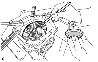
Coat 3 or 4 teeth at 3 different positions on the differential ring gear with Prussian blue.
-
Rotate the differential ring gear in both directions.
-
Inspect the tooth contact pattern.
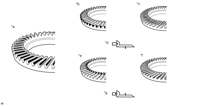
*a Proper Contact *b Heel Contact *c Face Contact *d Select an adjusting washer that will shift the drive pinion closer to the ring gear (*b, *c) *e Toe Contact *f Flank Contact *g Select an adjusting washer that will shift the drive pinion away from the ring gear (*e, *f) - - Note
Check the tooth contact pattern at 4 or more positions around the circumference of the differential ring gear.
-
-
INSPECT DIFFERENTIAL SIDE GEAR BACKLASH
-
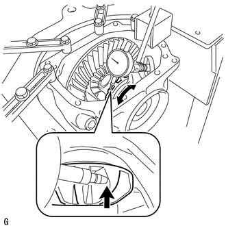
Place a dial indicator on the tip of a side gear tooth at a right angle. Hold the pinion gear in the rear differential case sub-assembly and check that the backlash is 0.15 mm (0.0059 in.) or less.
Backlash 0.15 mm (0.0059 in.) or less If the result is not as specified, replace the rear differential case sub-assembly with a new one.
-
-
INSPECT RUNOUT OF DIFFERENTIAL DRIVE PINION
-
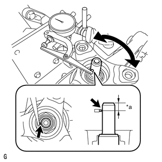
*a 10 mm (0.394 in.) Using a dial indicator, measure the runout of the differential drive pinion shaft at a position 10 mm (0.394 in.) away from the end of the shaft.
Maximum runout 0.08 mm (0.00315 in.) If the runout is more than the maximum, replace the differential drive pinion and differential ring gear.
-
-
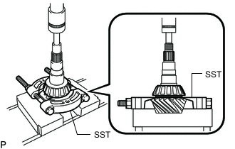
INSPECT DIFFERENTIAL DRIVE PINION PRELOAD
-
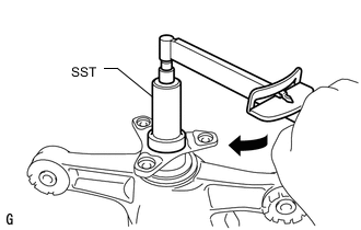
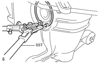
Using SST and a torque wrench, measure the starting torque of the differential drive pinion.
- SST
- 09229-55010
Differential drive pinion preload (at starting) 1.25 to 1.65 N*m (12.8 to 16.8 kgf*cm, 11.1 to 14.6 in.*lbf) Tech Tips
-
The backlash between the differential drive pinion and differential ring gear should allow enough movement of the differential drive pinion to allow this measurement to be performed.
-
Make sure not to include the preload of the differential ring gear (rear differential case sub-assembly) in the measurement of the differential drive pinion preload.
-
-
INSPECT TOTAL PRELOAD
-
Using SST and a torque wrench, measure the preload with the teeth of the differential drive pinion and differential ring gear in contact.
- SST
- 09229-55010
Total Preload (at Starting) 1.68 to 2.79 N*m (17.2 to 28.4 kgf*cm, 14.9 to 24.6 in.*lbf)
-
-
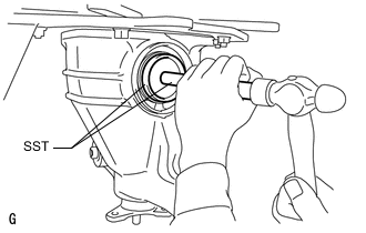
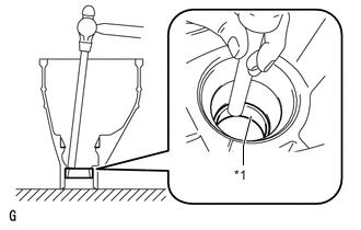
REMOVE REAR DRIVE SHAFT OIL SEAL LH
-
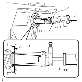
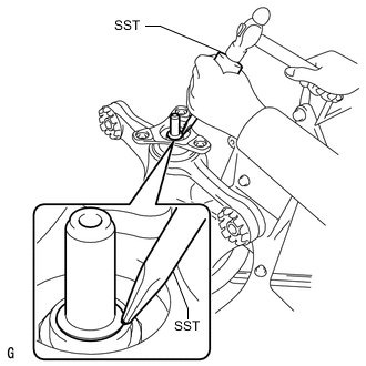
*1 Rear Drive Shaft Oil Seal LH Using SST, remove the rear drive shaft oil seal LH.
- SST
- 09308-00010
-
-
REMOVE REAR DRIVE SHAFT OIL SEAL RH
Tech Tips
Perform the same procedure as for the LH side.
-
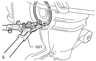
REMOVE REAR DIFFERENTIAL SIDE GEAR SHAFT SNAP RING (for RH Side)
-
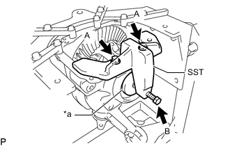
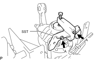
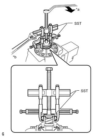
*a Disc Install SST to the differential carrier with the 2 bolts (A) so that the center of the SST disc is at the center of the rear differential case bearing (outer race).
- SST
- 09571-10200 ( 09571-01220, 09571-01230 )
-
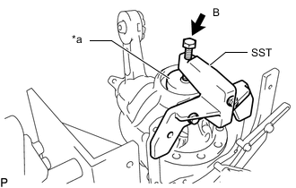
Tighten the SST bolt (B) until the SST disc lightly touches the rear differential case bearing outer race on the differential ring gear tooth side.
-
*a Turn Install a dial indicator to the rear differential carrier.
Tech Tips
Set the dial indicator as shown in the illustration.
-
Tighten the SST bolt and alter the shape of the rear differential carrier to create a 0.1 mm (0.00394 in.) clearance between the rear differential case bearing outer race and rear differential side gear shaft snap ring.
Note
Observe the dial indicator to ensure that the shape of the rear differential carrier does not change by more than 0.2 mm (0.00787 in.).
Tech Tips
A clearance of approximately 0.1 mm (0.00394 in.) between the rear differential case bearing outer race RH and rear differential side gear shaft snap ring is sufficient for the rear differential side gear shaft snap ring to move slightly.
-
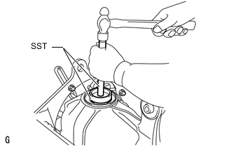
Using SST, remove the rear differential side gear shaft snap ring on the differential ring gear tooth side.
- SST
- 09905-00031
Tech Tips
-
For reassembly purposes, measure the thickness of the rear differential side gear shaft snap ring. Write down the result.
-
Put identification marks on each rear differential side gear shaft snap ring on the back side and tooth side of the ring gear, and keep them separate.
-
Remove the dial indicator and loosen the SST bolt.
Note
Do not remove SST.
-
-
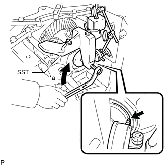
REMOVE REAR DIFFERENTIAL SIDE GEAR SHAFT SNAP RING (for LH Side)
-
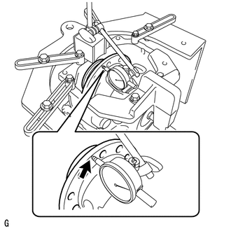
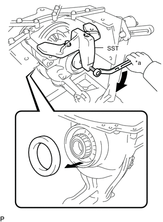
Using SST and a hammer, create a clearance between the rear differential case bearing outer race on the back surface of the differential ring gear and the rear differential side gear shaft snap ring.
- SST
- 09608-32010
- 09950-70010 ( 09951-07150 )
Tech Tips
The clearance is not visible, but tapping SST with a hammer 3 or 4 times should be enough.
-
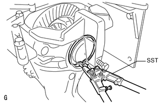
Using SST, remove the rear differential side gear shaft snap ring on the back surface of the differential ring gear.
- SST
- 09905-00031
Tech Tips
-
For reassembly purposes, measure the thickness of the rear differential side gear shaft snap ring. Write down the result.
-
Put identification marks on each rear differential side gear shaft snap ring on the back side and tooth side of the ring gear, and keep them separate.
-
-
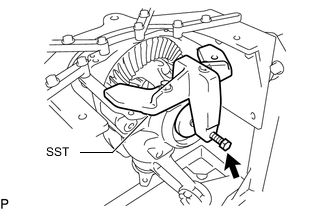
REMOVE REAR DIFFERENTIAL CASE BEARING (for LH Side)
-
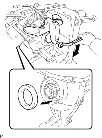
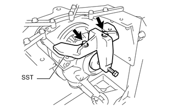
Tighten the SST bolt and push out the rear differential case bearing (outer race) on the back surface of the differential ring gear.
- SST
- 09571-10200 ( 09571-01220, 09571-01230 )
Note
Do not drop the rear differential case bearing outer race.
Tech Tips
Put identification marks on the rear differential case bearing outer race and rear differential side gear shaft snap ring to show the location for installation (back side or teeth side), or keep the races and snap rings separate so that they can be distinguished.
-
Remove the 2 bolts and SST.
-
-
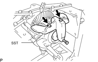
REMOVE REAR DIFFERENTIAL CASE BEARING (for RH Side)
-
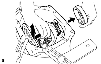
Raise the differential ring gear side of the rear differential case sub-assembly slightly to remove the rear differential case bearing (outer race) on the differential ring gear tooth side.
Note
Do not drop the rear differential case bearing outer race RH.
Tech Tips
Put identification marks on the rear differential case bearing outer race and rear differential side gear shaft snap ring to show the location for installation (back side or teeth side), or keep the races and snap rings separate so that they can be distinguished.
-
-
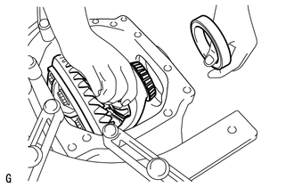
REMOVE REAR DIFFERENTIAL CASE SUB-ASSEMBLY
-
Remove the rear differential case sub-assembly as shown in the illustration.
Note
Do not damage the rear differential case bearing and differential ring gear.
-
-
REMOVE REAR DRIVE PINION NUT
-
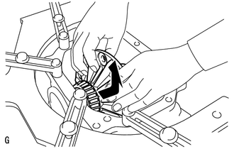
Using SST and a hammer, unstake the staked part of the rear drive pinion nut.
- SST
- 09930-00010
Note
-
Be sure to use SST with the tapered surface facing the differential drive pinion.
-
Do not grind the tip of SST with a grinder, etc.
-
Completely loosen the staked part of the rear drive pinion nut when removing it.
-
Do not damage the threads of the differential drive pinion.
-
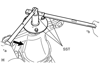
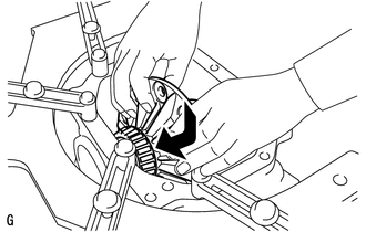
*a Turn *b Hold Using SST to hold the rear drive pinion companion flange, remove the rear drive pinion nut.
- SST
- 09229-55010
- 09330-00021
- 09950-30012 ( 09955-03040 )
CAUTION:
Hold the overhaul attachment during the operation.
Tech Tips
When securing SST and the companion flange, it is recommended to use M8 X P 1.25 bolts with a length of approximately 40 mm.
-
-
REMOVE REAR DRIVE PINION COMPANION FLANGE SUB-ASSEMBLY
-
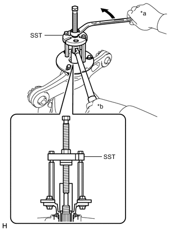
*a Turn *b Hold Using SST, remove the rear drive pinion companion flange sub-assembly.
- SST
- 09950-30012 ( 09951-03010, 09953-03010, 09954-03010, 09955-03040, 09956-03060 )
Note
Apply molybdenum grease to the threads of the SST center bolt (09953-03010) before use.
-
-
REMOVE REAR DIFFERENTIAL DUST DEFLECTOR
Tech Tips
Perform this procedure only when the rear differential dust deflector is damaged.
-
Using SST and a press, remove the rear differential dust deflector.
- SST
- 09950-60011 ( 09951-00440 )
- 09950-70010 ( 09951-07100 )
- 09950-00020
Note
Do not drop the rear drive pinion companion flange.
Tech Tips
Be sure to perform this operation while tightening the SST nuts to protect the contact surface of SST and the rear differential dust deflector.
-
-
REMOVE REAR DIFFERENTIAL CARRIER OIL SEAL
-
REMOVE REAR DIFFERENTIAL DRIVE PINION OIL SLINGER
-
Remove the rear differential drive pinion oil slinger.
-
-
REMOVE DIFFERENTIAL DRIVE PINION
-
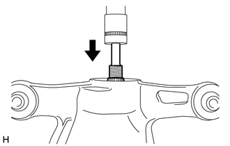
Using a press, remove the differential drive pinion from the rear differential carrier.
Note
Do not drop the differential drive pinion.
-
-
REMOVE REAR DIFFERENTIAL DRIVE PINION BEARING SPACER
-
Remove the rear differential drive pinion bearing spacer from the differential drive pinion.
-
-
REMOVE REAR DRIVE PINION FRONT BEARING
-
Remove the rear drive pinion front bearing (inner race) from the rear differential carrier.
-
*1 Rear Drive Pinion Front Bearing (Outer Race) Using a brass bar and hammer, tap out the rear drive pinion front bearing (outer race) from the differential carrier.
Tech Tips
If the bearing is damaged during removal, replace it.
-
-
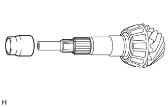
REMOVE REAR DRIVE PINION REAR BEARING
-
Using SST and a press, remove the rear drive pinion rear bearing (inner race) from the differential drive pinion.
- SST
- 09950-00020
Note
Do not drop the differential drive pinion.
Tech Tips
If either the differential drive pinion or differential ring gear is damaged, replace both as a set.
-
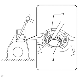
*1 Rear Differential Drive Pinion Plate Washer *2 Rear Drive Pinion Rear Bearing (Outer Race) Using a brass bar and hammer, remove the rear drive pinion rear bearing (outer race) from the rear differential carrier.
Tech Tips
Set the brass bar onto the concave portion of the differential carrier assembly. Lightly and uniformly tap the bearing and shim to remove them.
-
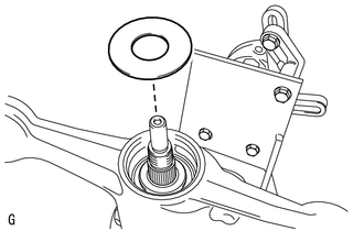
Remove the rear differential drive pinion plate washer.
Tech Tips
Make a note of the rear differential drive pinion plate washer thickness as a reference for assembly.
-
-
REMOVE DIFFERENTIAL RING GEAR
-
Hold the rear differential case sub-assembly in a vise between aluminum plates.
Note
Do not overtighten the vise.
-
*a Matchmark Put matchmarks on the differential ring gear and rear differential case sub-assembly.
-
Remove the 12 bolts.
-
Using a plastic-faced hammer, tap on the differential ring gear to remove it from the rear differential case sub-assembly.
Tech Tips
Place a cloth on the teeth side of the ring gear to prevent damage.
-
-
INSPECT RUNOUT OF REAR DIFFERENTIAL CASE SUB-ASSEMBLY
Tech Tips
Perform this procedure only when the runout of the differential ring gear exceeds the specified maximum value.
-
Insert the rear differential case sub-assembly from the differential ring gear tooth side to install the rear differential case sub-assembly as shown in the illustration.
Note
Do not damage the rear differential case bearing.
-
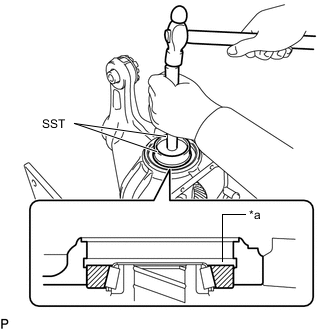
*a Groove Using SST and a hammer, install the rear differential case bearing (outer race) RH to the differential ring gear tooth side.
- SST
- 09608-32010
- 09950-70010 ( 09951-07200 )
Tech Tips
Tap in the rear differential case bearing outer race RH until half of the rear differential side gear shaft snap ring groove of the rear differential carrier can be seen.
-
Install SST to the differential carrier with the 2 bolts (A) so that the center of the SST disc is at the center of the rear differential case bearing (outer race).
- SST
- 09571-10200 ( 09571-01220, 09571-01230 )
-
*a Disc Tighten the SST bolt (B) until the SST disc lightly touches the rear differential case bearing (outer race) RH.
-
Using SST and a hammer, install the rear differential case bearing (outer race) LH to the differential ring gear back surface side.
- SST
- 09608-32010
- 09950-70010 ( 09951-07200 )
Tech Tips
Tap in the rear differential case bearing outer race LH until it touches the rear differential case bearing inner race roller.
-

Using SST, install the rear differential side gear shaft snap ring to the rear differential carrier on the differential ring gear back surface side.
- SST
- 09905-00031
-
Place a dial indicator on the rear differential case sub-assembly flange surface at a right angle.
-
Using a dial indicator, measure the rear differential case sub-assembly runout.
Maximum runout 0.05 mm (0.00197 in.) If the runout is more than the maximum, replace the rear differential case sub-assembly with a new one.
-
Using SST, remove the rear differential side gear shaft snap ring from the differential ring gear back surface side.
- SST
- 09905-00031
-
*a Turn Tighten the SST bolt to push out the rear differential case bearing (outer race) LH from the back surface of the differential ring gear.
- SST
- 09571-10200 ( 09571-01220, 09571-01230 )
Note
Do not drop the differential side bearing (outer race) LH.
-
Remove the 2 bolts and SST.
-
Raise the differential ring gear side of the rear differential case sub-assembly slightly to remove the differential side bearing (outer race) RH on the differential ring gear tooth side.
-
Remove the rear differential case sub-assembly from the rear differential carrier as shown in the illustration.
Note
Do not damage the rear differential case bearing.
-
-
REMOVE REAR DIFFERENTIAL CASE BEARING
Tech Tips
Perform this procedure only when replacing the rear differential case bearing or rear differential case sub-assembly.
-
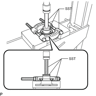
*a Turn *b Hold Using SST, remove the rear differential case bearing (inner races) LH and RH from the rear differential case sub-assembly.
- SST
- 09950-40011 ( 09951-04020, 09952-04010, 09953-04030, 09954-04010, 09955-04061, 09957-04010, 09958-04011 )
- 09950-60011 ( 09951-00350, 09951-00480, 09952-06010 )
Note
-
Do not deform the bearing cage if the bearing is to be reused.
-
Hook the claws of SST to the rear differential case bearing inner race.
-
Apply molybdenum grease to the threads and tip of the SST center bolt (09953-04030) before use.
-
-
INSPECT DIFFERENTIAL SIDE GEAR BACKLASH
-
Secure the rear differential case sub-assembly in a vise between aluminum plates.
Note
Do not overtighten the vise.
-
Place a dial indicator on the tip of a side gear tooth at a right angle. Hold the pinion gear in the rear differential case sub-assembly and check that the backlash is 0 mm (0 in.).
If the result is not as specified, replace the rear differential case sub-assembly with a new one.
-