FRONT AIR CONDITIONING UNIT INSTALLATION
PROCEDURE
INSTALL INSTRUMENT PANEL REINFORCEMENT ASSEMBLY
Attach the 2 claws to install the instrument panel reinforcement assembly.
Install the 5 bolts.
9.8 N*m
100 kgf*cm
87 in.*lbf
INSTALL INSTRUMENT PANEL REINFORCEMENT ASSEMBLY WITH AIR CONDITIONING UNIT ASSEMBLY
Temporarily install the instrument panel reinforcement assembly with air conditioning unit assembly with the 2 bolts.
Using a 8 mm hexagon wrench, tighten the 2 collars.
27 N*m
275 kgf*cm
20 ft.*lbf
Using a T40 "TORX" socket, install the 5 "TORX" bolts in the order shown in the illustration.
27 N*m
275 kgf*cm
20 ft.*lbf
Tighten the 2 bolts in the order shown in the illustration.
for bolt A
20 N*m
204 kgf*cm
14 ft.*lbf
Install the 5 caps.
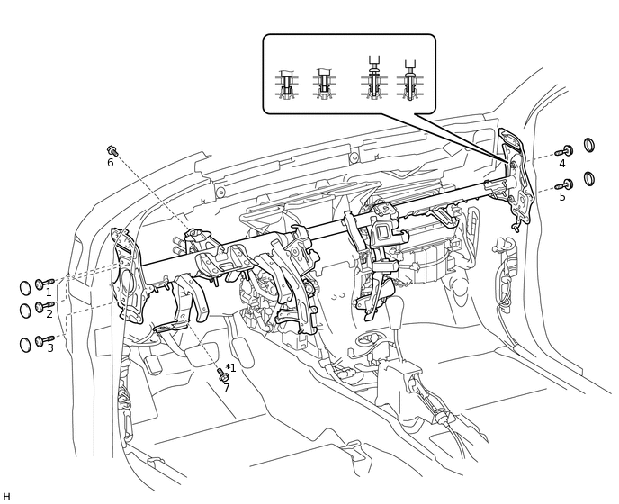
*1
Bolt A
-
-
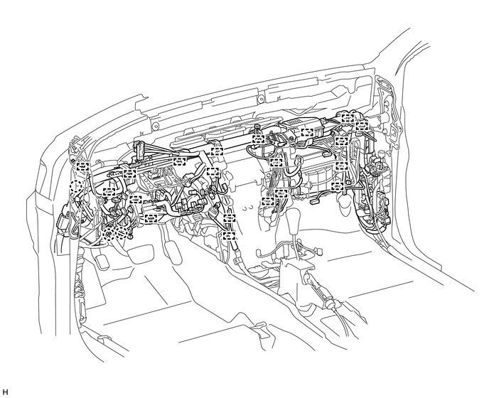
Attach the clamps and connect the connectors to the wire harness.
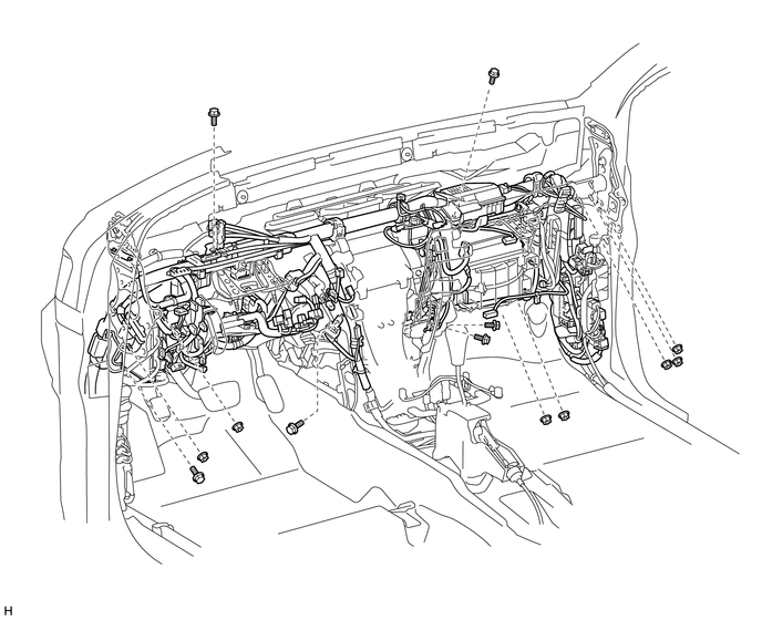
Install the wire harness with the 6 bolts and 7 nuts.
INSTALL NO. 1 AIR DUCT SUB-ASSEMBLY
Attach the 3 claws to install the No. 1 air duct sub-assembly.
INSTALL NO. 2 AIR DUCT SUB-ASSEMBLY
Attach the 2 claws to install the No. 2 air duct sub-assembly.
Install the screw.
INSTALL NO. 1 INSTRUMENT PANEL BRACE MOUNTING BRACKET LH
Install the No. 1 instrument panel brace mounting bracket LH with the 2 nuts and bolt.
INSTALL NO. 1 INSTRUMENT PANEL BRACE MOUNTING BRACKET RH
Install the No. 1 instrument panel brace mounting bracket RH with the 2 nuts and bolt.
INSTALL NO. 1 CONSOLE BOX DUCT (for Single Air Conditioning System)
Install the No. 1 console box duct with the clip.
INSTALL REAR NO. 3 AIR DUCT
Attach the 6 claws and 3 clamps to install the rear No. 3 air duct.
INSTALL REAR NO. 1 AIR DUCT
Attach the 6 claws and 3 clamps to install the rear No. 1 air duct.
INSTALL FRONT FLOOR CARPET ASSEMBLY
Install the front floor carpet assembly.
INSTALL FRONT SEAT ASSEMBLY LH
INSTALL FRONT SEAT ASSEMBLY RH
INSTALL STEERING COLUMN ASSEMBLY
INSTALL INSTRUMENT PANEL SUB-ASSEMBLY
INSTALL WINDSHIELD WIPER MOTOR ASSEMBLY
CONNECT HEATER WATER INLET HOSE AND OUTLET HOSE
Connect the 2 heater water hoses.
Using pliers, grip the claws of the clips and slide the 2 clips.
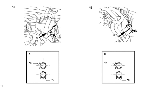
*A
for 1UR-FE
*B
for 1GR-FE
*a
Brown Marking
*b
Green Marking
*c
Blue Marking
-
-
CONNECT AIR CONDITIONING TUBE AND ACCESSORY ASSEMBLY
Install the grommet.
-
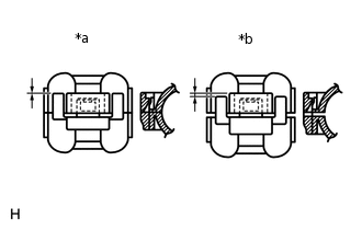
*a
CORRECT
*b
INCORRECT
Connect the air conditioning tube and accessory assembly with the piping clamp.
Note:After the connection, check that the claw of the piping clamp is attached.
CONNECT CABLE TO NEGATIVE BATTERY TERMINAL
Note:When disconnecting the cable, some systems need to be initialized after the cable is reconnected (Click hereClick hereClick hereClick here).
CHARGE REFRIGERANT
ADD ENGINE COOLANT
for 1UR-FE:
for 1GR-FE:
WARM UP ENGINE
CHECK FOR COOLANT LEAK
for 1UR-FE:
for 1GR-FE:
CHECK FOR REFRIGERANT GAS LEAK
CHECK SRS WARNING LIGHT