ENTRY LOCK AND UNLOCK SWITCH REMOVAL
CAUTION / NOTICE / HINT
Use the same procedure for the RH side and LH side.
The following procedure is for the LH side.
PROCEDURE
PRECAUTION
Note:After turning the ignition switch off, waiting time may be required before disconnecting the cable from the negative (-) battery terminal. Therefore, make sure to read the disconnecting the cable from the negative (-) battery terminal notices before proceeding with work.
DISCONNECT CABLE FROM NEGATIVE BATTERY TERMINAL
Note:When disconnecting the cable, some systems need to be initialized after the cable is reconnected.
REMOVE POWER WINDOW REGULATOR MASTER SWITCH ASSEMBLY WITH FRONT DOOR UPPER ARMREST BASE PANEL (for Driver Side)
REMOVE POWER WINDOW REGULATOR SWITCH ASSEMBLY WITH FRONT DOOR UPPER ARMREST BASE PANEL (for Front Passenger Side)
REMOVE FRONT DOOR TRIM COVER
REMOVE FRONT DOOR LOWER FRAME BRACKET GARNISH
REMOVE FRONT DOOR TRIM BOARD SUB-ASSEMBLY
REMOVE FRONT DOOR SERVICE HOLE COVER
REMOVE FRONT DOOR OUTSIDE HANDLE COVER WITH LOCK CYLINDER ASSEMBLY (for Driver Side)
REMOVE FRONT DOOR OUTSIDE HANDLE COVER (for Front Passenger Side)
REMOVE FRONT DOOR OUTSIDE HANDLE ASSEMBLY
-
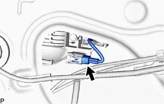
Disconnect the connector.
-
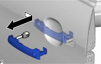
Remove the front door outside handle assembly as shown in the illustration.
-