DYNAMIC TORQUE CONTROL AWD SYSTEM
-
FUNCTION OF MAIN COMPONENTS
Component Function Transfer Drive force input into the differential is redirected 90 degrees and output to the propeller shaft by the transfer. Electro Magnetic Control Coupling Sub-assembly Electromagnetic Solenoid Distributes drive torque in accordance with the amperage applied by the 4WD ECU assembly. Throttle Body with Motor Assembly Throttle Position Sensor Detects the throttle valve position and outputs it to the ECM. Crank Position Sensor Detects the engine speed and outputs it to the ECM. Speed Sensor Detects the wheel speed of each wheel. Steering Sensor Detects the direction and angle of the steering wheel. Park/Neutral Position Switch Assembly Detects the shift position of the transaxle and outputs it to the ECM. Stop Light Switch Assembly Detects when the brake pedal is depressed. Integration Control and Panel Assembly*1 AWD LOCK Mode Switch Switches to AWD LOCK mode. Combination Switch Assembly*2 4WD ECU Assembly
-
Controls the amperage applied to the electromagnetic solenoid based on signals provided by the ECUs, sensors and switches in order to optimally distribute drive torque in accordance with driving conditions.
-
Turns AWD mode off when a parking brake ON signal is received from the main body ECU (multiplex network body ECU).
-
Turns AWD mode off when a shift position signal (P or N) is received from the ECM.
ECM Outputs signals such as the shift position signal, throttle position signal and engine speed signal to the 4WD ECU assembly. Brake Actuator Assembly Skid Control ECU Outputs signals such as the vehicle speed signal, brake pedal depressing signal and parking brake signal to the 4WD ECU assembly. Airbag Sensor Assembly*3 Yawrate Sensor Detects the vehicle's yaw rate, longitudinal and lateral acceleration and deceleration. Acceleration Sensor Yawrate Sensor Assembly*4 Combination Meter Assembly Multi-information Display
-
Displays a warning message to inform or warn the driver of the system condition in accordance with signals from the 4WD ECU assembly.
-
Displays the distribution of drive torque to the front and rear wheels by the AWD system.
Master Warning Light Illuminates to warn the driver if a malfunction occurs in the AWD system. AWD LOCK Mode Indicator Light Illuminates to inform the driver that AWD lock mode is engaged. Buzzer Warns the driver by sounding when a message is shown on the multi-information display. *1: Models with 8AR-FTS Engine
*2: Models with 2GR-FKS Engine
*3: Models without VDIM
*4: Models with VDIM
-
-
SYSTEM CONTROL
Control Function Start Off Control Performs control which distributes drive force to the rear wheels to ensure traction performance when starting off and avoid the tight corner braking phenomenon*, which occurs during cornering. Normal Control
-
Performs control which distributes drive force to the rear wheels to ensure acceleration performance when driving straight ahead and cornering stability.
-
When a stable driving condition has been determined, reduces drive force distribution to the rear wheels to improve fuel economy.
Lock Mode Control When starting off in Lock mode, the maximum amount of drive force is transmitted to the rear wheels to improve driving performance on surfaces where it is easy for the vehicle to get stuck, such as sandy soil, snow-covered roads, etc. Cornering Control Uses pre-torque control, which is based on driver operation input, and yawrate feedback control, which is based on the vehicle status, to achieve the tracing performance desired by the driver. Braking Control When braking, cancels AWD to improve braking effectiveness. VSC Cooperative Control When accelerating during cornering on slippery surfaces, etc., the dynamic torque control AWD system and VSC function cooperate to perform control which achieves smoother acceleration and higher stability compared to previous TRC and VSC functions. As a result, smooth acceleration during turning is made possible. Tech Tips
*: Tight corner braking phenomenon: a phenomenon in which a AWD vehicle may lurch and decelerate due to a rotational speed difference between the front and rear wheels, such as during low-speed cornering in AWD mode.
-
Start Off Control
-
The system ensures start-off performance by optimally distributing engine drive torque to the front and rear wheels.
-
To prevent the tight corner braking phenomenon from occurring during low-speed cornering, the system reduces the amount of torque distributed to the rear wheels.
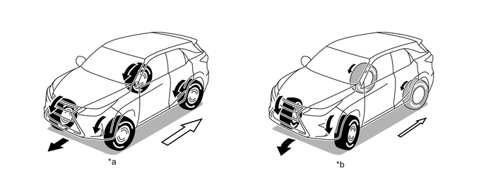
*a Straightline Driving *b Low-speed Cornering 
Torque Distribution to Rear Wheels - -
-
-
Normal Control
-
During normal driving, when the system judges that the vehicle is traveling steadily, it reduces the amount of torque distribution to the rear wheels. This allows the vehicle to operate in conditions similar to front-wheel-drive, improving fuel economy.
-
The system optimizes torque distribution to the rear wheels to ensure both excellent straightline acceleration performance and excellent driving stability while cornering.
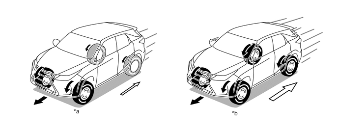
*a Steady Driving *b Straightline Acceleration Torque Distribution to Rear Wheels - -
-
-
Cornering Control
-
The desired driving path of the driver is estimated using information such as the vehicle speed, steering angle, etc., to change drive force distribution according to driving conditions. As a result, excellent driving stability is ensured.
-
Pre-torque control, which is based on driver operation input, and yawrate feedback control, which is based on the vehicle status, are used to correct vehicle oversteer and understeer and achieve the tracing performance desired by the driver.
-
Pre-torque control is linked with driver steering wheel operations and distributes drive force to the rear wheels to improve steering performance when entering a corner (front and rear drive force distribution is 90:10).
-
Yawrate feedback control performs high-speed computation of the ideal yaw rate (calculated by the 4WD ECU assembly when the vehicle is in motion) and actual yaw rate, detects vehicle steering characteristics (oversteer or understeer), and performs optimal control to distribute drive force to the front or rear wheels if required for correction (front and rear drive force distribution changes from 90:10 to 50:50).
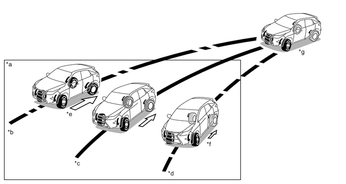
*a Yawrate Feedback Control *b Understeer Tendency *c Target Line *d Oversteer Tendency *e Drive Force Distribution to Rear Wheels Increased *f Drive Force Distribution to Rear Wheels Reduced *g Pre-torque Control - -
-
-
AWD Control in AWD LOCK Mode
-
When the vehicle is being driven in gravel or sand and more traction is required, the driver can select Lock mode by operating the AWD LOCK mode switch. Thus, this mode achieves optimal control in accordance with the driving conditions and transmits as much drive torque as possible to the rear wheels, in a mode that is similar to the locked AWD mode.
-
-
-
FUNCTION
-
AWD Operation Condition Display
-
With this display, even on a slippery road, the user can monitor the condition of the AWD control system as it operates in accordance with the surrounding conditions. This contributes to an improved feeling of safety provided by AWD systems.
-
AWD operation condition display mode can be enabled or disabled by operating the steering pad switch assembly.
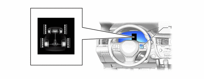
*1 Steering Pad Switch Assembly - - -
AWD Display
-
The ratio of drive torque distributed to the front and rear wheels varies according to driving conditions.
-
The drive torque distributed to each of the front and rear wheels is displayed using segments. If the drive torque is large, more segments are illuminated. If the drive torque is small, less segments are illuminated.
-
When the drive torque to the rear wheels is large, the AWD system judges that more stability and roadholding performance is required and AWD control is engaged.
-
When the drive torque to the rear wheels is small, the AWD system judges that the vehicle is being driven stably and AWD control is suppressed for improved fuel efficiency.
-
-
-
-
FAIL-SAFE
-
When there is a possibility of causing damage to the drivetrain due to a malfunction in the AWD system or rough driving, the system illuminates or blinks the master warning light and displays the message on the multi-information display to inform the driver and stops AWD control.
Vehicle Condition Control Combination Meter Assembly Master Warning Light Multi-information Display AWD system malfunction 2WD driving
(control prohibited)
Illuminates AWD System
Malfunction
2WD Mode
Engaged
Visit Your Dealer
AWD excess driving (warning before AWD control is prohibited) AWD driving Blinks AWD System
Overheated
Switching to
2WD Mode
AWD excess driving 2WD driving
(control prohibited)
Blinks AWD System
Overheated
2WD Mode
Engaged
-
When the master warning light illuminates or blinks as a message is displayed on the multi-information display, perform the following procedures.
-
Decelerate until the master warning light turns off.
-
Stop the vehicle until the master warning light turns off (idle the engine).
-
-
When a stable system condition is determined, AWD control automatically resumes.
-
-
DIAGNOSIS
-
Furthermore, the master warning light in the combination meter assembly will illuminate and a warning message will be displayed on the multi-information display to inform the driver.
-
For details of the DTCs that are stored in 4WD ECU assembly memory, refer to the Repair Manual.
-