MANUAL TRANSAXLE UNIT REASSEMBLY
CAUTION / NOTICE / HINT
When the front differential case front tapered roller bearing (outer race) is removed, the front differential case front tapered roller bearing and front differential case front tapered roller bearing (outer race) need to be replaced.
When the front differential case front tapered roller bearing (outer race) is removed, the front differential case front tapered roller bearing and front differential case front tapered roller bearing (outer race) can be reused.
When the front differential case rear tapered roller bearing (outer race) is removed, the front differential case rear tapered roller bearing and front differential case rear tapered roller bearing (outer race) need to be replaced.
When the front differential case rear tapered roller bearing (outer race) is removed, the front differential case rear tapered roller bearing and front differential case rear tapered roller bearing (outer race) can be reused.
PROCEDURE
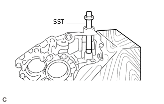
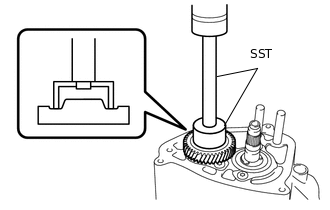
INSTALL FRONT DIFFERENTIAL CASE FRONT TAPERED ROLLER BEARING (OUTER RACE)
-
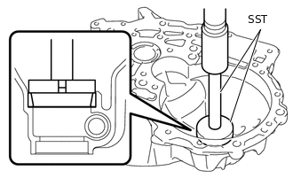
Using SST and a press, install a new front differential case front tapered roller bearing (outer race) to the No. 1 transaxle (MTM) case.
09950-60010
09951-00640
09950-70010
09951-07150
-
INSTALL FRONT DRIVE SHAFT OIL SEAL RH
Coat the lip of a new front drive shaft oil seal RH with MP grease.
-
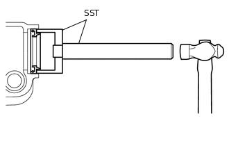
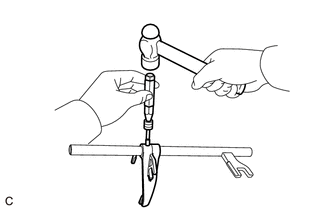
Using SST and a hammer, install the front drive shaft oil seal RH to the No. 1 transaxle (MTM) case.
09950-70010
09951-07150
09710-30021
09710-03101
Note:Be careful not to damage the lip of the front drive shaft oil seal RH.
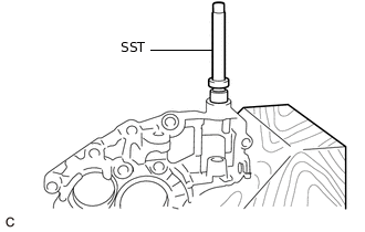
INSTALL FRONT DIFFERENTIAL CASE REAR TAPERED ROLLER BEARING (OUTER RACE)
-
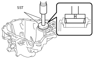
Using SST and a press, install a new front differential case rear tapered roller bearing (outer race) to the manual transmission case.
09950-60010
09951-00640
09950-70010
09951-07150
-
INSTALL FRONT DRIVE SHAFT OIL SEAL LH
Coat the lip of a new front drive shaft oil seal LH with MP grease.
-
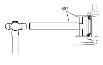
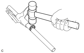
Using SST and a hammer, install the front drive shaft oil seal LH to the manual transmission case.
09950-70010
09951-07150
09710-30050
Note:Be careful not to damage the lip of the front drive shaft oil seal LH.
INSTALL NO. 2 MANUAL TRANSMISSION CASE STRAIGHT PIN
-
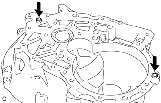
Install 2 new No. 2 manual transmission case straight pins to the No. 1 transaxle (MTM) case.
-
INSTALL NO. 1 MANUAL TRANSMISSION CASE STRAIGHT PIN
-
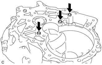
Install 3 new No. 1 manual transmission case straight pins to the No. 1 transaxle (MTM) case.
-
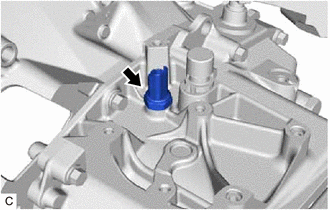
INSTALL BREATHER PLUG
-
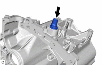
Install the breather plug to the manual transmission case.
-
INSTALL BREATHER PROTECTOR
-
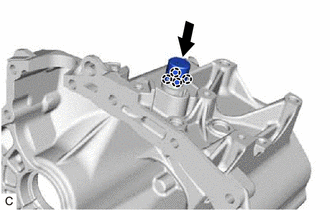
Engage the 4 claws to install the breather protector to the breather plug.
-
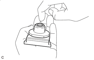
INSTALL NO. 2 SHIFT AND SELECT LEVER SHAFT NEEDLE ROLLER BEARING
-
Using SST, install a new No. 2 shift and select lever shaft needle roller bearing to the No. 2 transaxle (MTM) case.
0317-MAZ
0317-AQ
-
INSTALL NO. 1 SHIFT AND SELECT LEVER SHAFT NEEDLE ROLLER BEARING
-
Using SST, install a new No. 1 shift and select lever shaft needle roller bearing to the No. 2 transaxle (MTM) case.
0317-MAZ
0317-AQ
-
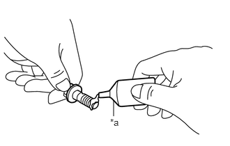
INSTALL REVERSE SHIFT ARM BRACKET
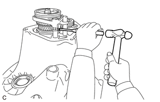
Using an air riveter or a hand riveter, install the reverse shift arm bracket to the No. 2 transaxle (MTM) case with a new rivet.
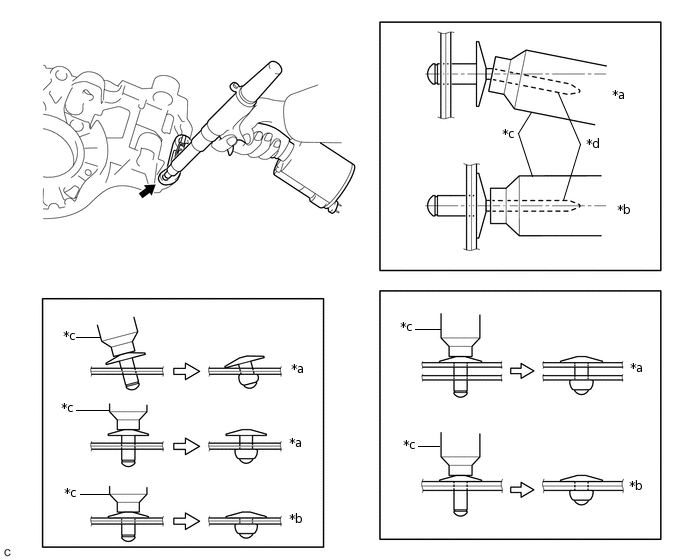
*a
Incorrect
*b
Correct
*c
Riveter
*d
Mandrel
Note:Do not pry on the rivet with the riveter, as this will cause damage to the riveter and mandrel.
Confirm that the rivet is seated properly against the reverse shift arm bracket.
Do not tilt the riveter when installing the rivet to the reverse shift arm bracket.
Do not leave a gap between the rivet head and reverse shift arm bracket.
Do not leave a gap between the reverse shift arm bracket and No. 2 transaxle (MTM) case. Firmly hold the reverse shift arm bracket and No. 2 transaxle (MTM) case together while installing the rivets.
Tip:If the rivet cannot be cut, pull it once and cut it.
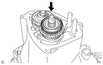
INSTALL DIFFERENTIAL CASE ASSEMBLY
-
Coat the differential case assembly with gear oil, and install it to the No. 1 transaxle (MTM) case.
-
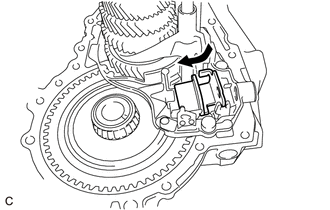
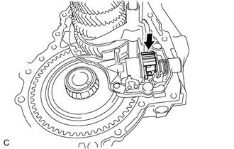
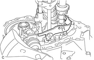
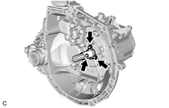
INSTALL NO. 2 REVERSE SHIFT ARM PIN
Install the spring to the No. 1 transaxle (MTM) case.
-
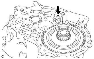
Install the No. 2 reverse shift arm pin to the No. 1 transaxle (MTM) case.
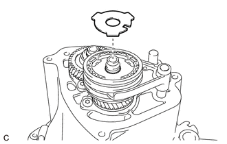
INSTALL TRANSMISSION MAGNET
-
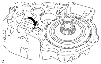
Clean and install the transmission magnet to the No. 1 transaxle (MTM) case.
-
INSTALL NO. 2 TRANSAXLE (MTM) CASE
-
*a
Adhesive
Clean and degrease the bolts and installation holes in the No. 1 transaxle (MTM) case.
Apply adhesive to the 2 or 3 threads on the end of the 11 bolts.
Adhesive
Toyota Genuine Adhesive 1324, Three Bond 1324 or equivalent
Note:In order to ensure proper installation of the bolts, apply adhesive to the bolts and install them within 10 minutes of adhesive application.
-
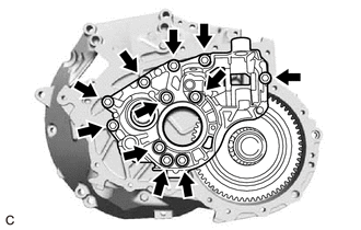
Using a T50 "TORX" socket wrench, install the No. 2 transaxle (MTM) case to the No. 1 transaxle (MTM) case with the 11 bolts.
50 N*m
510 kgf*cm
37 ft.*lbf
-
INSTALL NO. 2 SHIFT FORK
Install the No. 2 shift fork to the No. 2 gear shift fork shaft.
-
Using a 5 mm pin punch and a hammer, install a new pin to the No. 2 shift fork.
INSTALL NO. 1 GEAR SHIFT FORK
Install the No. 1 shift fork to the No. 3 gear shift fork shaft.
-
Using a plastic hammer, install a new shift fork shaft E ring to the No. 3 gear shift fork shaft.
INSTALL NO. 3 GEAR SHIFT FORK
Install the No. 3 gear shift fork to the output shaft assembly.
INSTALL NO. 2 GEAR SHIFT FORK
Install the No. 2 gear shift fork to the input shaft assembly.
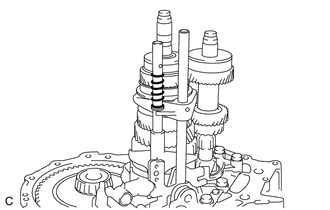
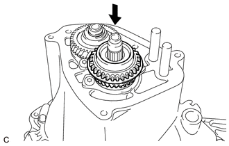
INSTALL INPUT SHAFT ASSEMBLY AND OUTPUT SHAFT ASSEMBLY
-
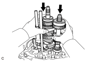
Coat sliding and rotating surfaces of the input shaft assembly and output shaft assembly with gear oil, and temporarily install them to the No. 1 transaxle (MTM) case.
-
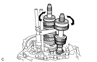
While turning the input shaft assembly and output shaft assembly, install them to the No. 1 transaxle (MTM) case.
-
Install the gear-box control lever spring to the No. 3 gear shift fork.
-
INSTALL SHIFT INTER LOCK PLATE
-
Install the shift inter lock plate to the No. 2 transaxle (MTM) case.
-
INSTALL SHIFT AND SELECT LEVER SHAFT SPRING
-
Install the shift and select lever shaft spring to the No. 2 transaxle (MTM) case.
-
INSTALL SHIFT AND SELECT LEVER SHAFT DUST BOOT

Lithium Soap Base Glycol Grease
Apply lithium soap base glycol grease to the inside of the shift and select lever shaft dust boot.
-
Install the shift and select lever shaft dust boot to the shift and select lever.
INSTALL SHIFT AND SELECT LEVER SUB-ASSEMBLY
-
Install the shift and select arm to the No. 2 transaxle (MTM) case.
-
Install the shift and select lever to the No. 2 transaxle (MTM) case.
-
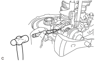
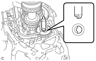
Using a 5 mm pin punch and a hammer, install a new shift and select lever shaft straight pin to the shift and select lever sub-assembly.
-
INSTALL REVERSE SHIFT ARM
-
Install the reverse shift arm to the No. 2 transaxle (MTM) case.
-
Install the No. 1 reverse shift arm pin to the No. 2 transaxle (MTM) case.
-
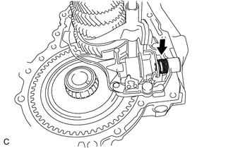
INSTALL REVERSE IDLER GEAR SUB-ASSEMBLY
-
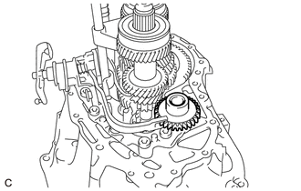
Install the reverse idler gear sub-assembly to the No. 2 transaxle (MTM) case.
-
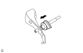
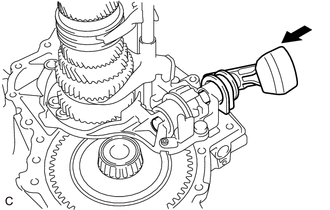
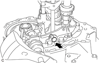
INSTALL REVERSE IDLER GEAR SHAFT
Coat the reverse idler gear shaft with gear oil.
-
Pass the reverse idler gear shaft through the reverse idler gear sub-assembly, and then install it to the No. 1 transaxle (MTM) case.
Tip:Align the key of the reverse idler gear shaft with the keyway when installing the reverse idler gear shaft.
After installation, confirm that the reverse idler gear shaft cannot be turned.
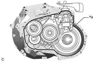
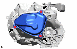
INSTALL MANUAL TRANSMISSION CASE
Remove any remaining seal packing (FIPG) from the contact surfaces of the manual transmission case and No. 1 transaxle (MTM) case.
Note:Make sure that there is no gear oil on the contact surfaces.
-
*a
Seal Packing (FIPG)
(Seal Width: 1.2 mm (0.0472 in.))
Apply seal packing (FIPG) to the manual transmission case.
Seal Packing (FIPG)
Toyota Genuine Seal Packing 1281, Three Bond 1281 or equivalent
Note:Install the parts within 10 minutes of application. Otherwise, the seal packing (FIPG) must be removed and reapplied.
Apply seal packing (FIPG) in a continuous line (width 1.2 mm (0.0472 in.)) to the sealing surface of the manual transmission case.
-
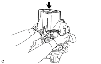
Install the manual transmission case to the No. 1 transaxle (MTM) case.
-
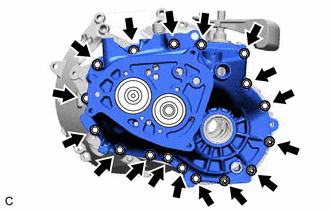
Install the 17 bolts to the manual transmission case.
23 N*m
235 kgf*cm
17 ft.*lbf
INSTALL REAR (MTM) BEARING RETAINER
-
*a
Adhesive
Clean and degrease the bolts and installation holes in the manual transmission case.
Apply adhesive to the 2 or 3 threads on the end of the 4 bolts.
Adhesive
Toyota Genuine Adhesive 1324, Three Bond 1324 or equivalent
Note:In order to ensure proper installation of the bolts, apply adhesive to the bolts and install them within 10 minutes of adhesive application.
-
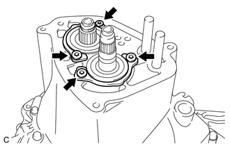
Using a T40 "TORX" socket wrench, install the rear (MTM) bearing retainer (for input shaft assembly) and rear (MTM) bearing retainer (for output shaft assembly) to the manual transmission case with the 4 bolts.
18 N*m
184 kgf*cm
13 ft.*lbf
-
INSTALL 5TH GEAR
-
Using SST and a press, install the 5th gear to the input shaft.
09710-30021
09710-03071
09950-70010
09951-07150
Install the 5th gear thrust washer to the input shaft assembly.
Using a snap ring expander, install the 5th gear shaft snap ring to the input shaft assembly.
-
INSTALL 5TH DRIVEN GEAR
-
Install the 5th driven gear to the output shaft assembly.
-
INSTALL NO. 2 SYNCHRONIZER RING SET
-
Install the No. 2 synchronizer ring set to the 5th driven gear.
-
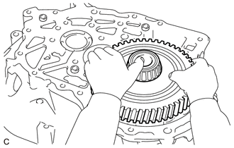
INSTALL NO. 3 SYNCHRONIZER HUB ASSEMBLY
Tip:Perform this procedure only when replacing the 3 synchromesh shifting key balls, 3 compression springs or 3 No. 2 synchromesh shifting keys.
Apply gear oil to the No. 3 transmission hub sleeve and No. 3 transmission clutch hub.
Align the No. 3 transmission clutch hub and No. 3 transmission hub sleeve as shown in the illustration and install them.
Note:When reusing the No. 3 transmission clutch hub and No. 3 transmission hub sleeve, make sure to align the matchmarks during installation.
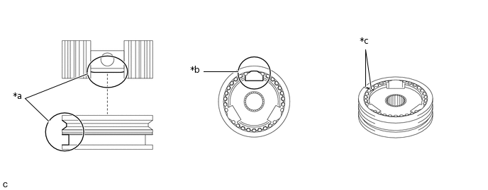
*a
Face the cutout of the No. 3 transmission clutch hub and groove of the No. 3 transmission hub sleeve upward.
*b
Align the grooves of the No. 3 transmission clutch hub and No. 3 transmission hub sleeve.
*c
Matchmark
-
-
Temporarily install the No. 3 transmission hub sleeve to the No. 3 transmission clutch hub.
Install the 3 No. 2 synchromesh shifting keys to the No. 3 transmission clutch hub.
Install the 3 compression springs to the No. 3 transmission clutch hub.
Place the 3 synchromesh shifting key balls into the holes of the No. 2 synchromesh shifting keys and install the No. 3 transmission hub sleeve to the No. 3 transmission clutch hub while pushing in the synchromesh shifting key balls.
Note:Take care to prevent the synchromesh shifting key balls and compression spring from scattering.
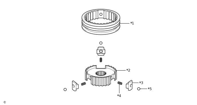
*1
No. 3 Transmission Hub Sleeve
*2
No. 3 Transmission Clutch Hub
*3
No. 2 Synchromesh Shifting Key
*4
Compression Spring
*5
Synchromesh Shifting Key Ball
-
-
INSTALL NO. 3 TRANSMISSION CLUTCH HUB WITH NO. 3 TRANSMISSION HUB SLEEVE
-
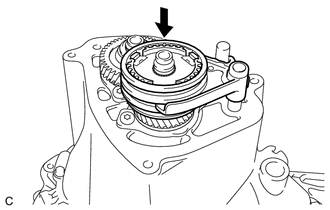
Install the No. 3 gear shift fork with No. 3 synchronizer hub assembly to the output shaft assembly.
-
Install the spacer to the output shaft assembly.
-
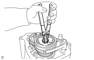
Using a snap ring expander, install the No. 3 transmission clutch hub shaft snap ring to output shaft assembly.
-
Using a 5 mm pin punch and a hammer, install the pin to the No. 3 shift fork.
-
INSTALL MANUAL TRANSMISSION CASE COVER SUB-ASSEMBLY
-
Install the manual transmission case cover sub-assembly and a new manual transmission case cover gasket to the manual transmission case with 3 bolts.
22 N*m
224 kgf*cm
16 ft.*lbf
-
INSTALL DRAIN (MTM) PLUG SUB-ASSEMBLY
-
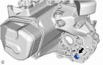
Using a 7 mm square wrench, install the drain (MTM) plug sub-assembly and a new drain plug (MTM) gasket to the manual transmission case.
33 N*m
337 kgf*cm
24 ft.*lbf
-
INSTALL MANUAL TRANSMISSION FILLER PLUG
-
*a
Adhesive
Clean and degrease the manual transmission filler plug and installation hole in the manual transmission case.
Apply adhesive to the 2 or 3 threads on the end of the manual transmission filler plug.
Adhesive
Toyota Genuine Adhesive 1344, Three Bond 1344 or equivalent
Note:In order to ensure proper installation of the manual transmission filler plug, apply adhesive to the manual transmission filler plug and install them within 10 minutes of adhesive application.
-
Using a 27 mm socket wrench, install the manual transmission filler plug to the manual transmission case.
-
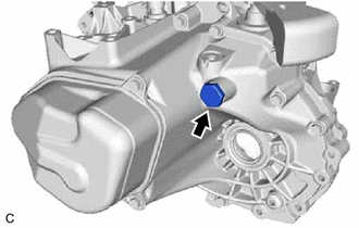
INSTALL BACK-UP LIGHT SWITCH ASSEMBLY
-
Using a 22 mm deep socket wrench, install the back-up light switch assembly to the manual transmission case.
25 N*m
255 kgf*cm
18 ft.*lbf
-
INSTALL CLUTCH BUFFER GUIDE BUSH
-
*a
Adhesive
Clean and degrease the bolts and installation holes in the No. 1 transaxle (MTM) case.
Apply adhesive to the 2 or 3 threads at the end of each of 3 bolts.
Adhesive
Toyota Genuine Adhesive 1324, Three Bond 1324 or equivalent
Note:In order to ensure proper installation of the bolts, apply adhesive to the bolts and install them within 10 minutes of adhesive application.
Coat the lip of a new clutch buffer guide bush with MP grease.
-
Using an 8 mm deep socket wrench, install the clutch buffer guide bush to the No. 1 transaxle (MTM) case with the 3 bolts.
10 N*m
102 kgf*cm
7 ft.*lbf
-
INSTALL SPEEDOMETER DRIVEN HOLE COVER SUB-ASSEMBLY
Install a new O-ring to the speedometer driven hole cover sub-assembly.
-

Using a 6 mm hexagon wrench, install the speedometer driven hole cover sub-assembly to the No. 1 transaxle (MTM) case with the bolt.
INSTALL CLUTCH RELEASE FORK BOOT
INSTALL CLUTCH RELEASE FORK SUB-ASSEMBLY