SFI SYSTEM, Diagnostic DTC:P2122,P2123,P2127 and P2128
| DTC Code | DTC Name |
|---|---|
| P2122 | Throttle / Pedal Position Sensor / Switch "D" Circuit Low Input |
| P2123 | Throttle / Pedal Position Sensor / Switch "D" Circuit High Input |
| P2127 | Throttle / Pedal Position Sensor / Switch "E" Circuit Low Input |
| P2128 | Throttle / Pedal Position Sensor / Switch "E" Circuit High Input |
DESCRIPTION
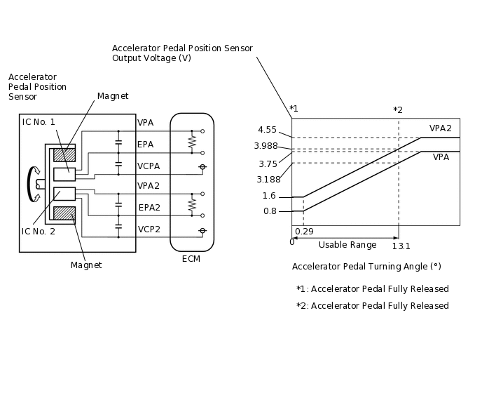
The accelerator pedal position sensor is mounted on the accelerator pedal sensor assembly and detects the opening angle of the accelerator pedal. Since this sensor is electronically controlled with Hall-effect elements, accurate control and reliability can be obtained. It has 2 sensors to detect the accelerator position and malfunctions of the accelerator position sensor.
In the accelerator pedal position sensor, the voltage applied to pedal terminals VPA and VPA2 of the ECM changes between 0 V and 5 V in proportion to the opening angle of the accelerator pedal. The VPA is a signal which indicates the actual accelerator pedal opening angle and is used for engine control, and the VPA2 is a signal which indicates the information about the opening angle and is used for detecting malfunctions. The ECM judges the current opening angle of the accelerator pedal using signals from terminals VPA and VPA2, and the ECM controls the throttle motor based on these signals.
This electrical throttle system does not use a throttle cable.
This accelerator pedal position sensor is a non-contact type.
DTC No. |
Detection Item |
DTC Detection Condition |
Trouble Area |
MIL |
Memory |
|---|---|---|---|---|---|
P2122 |
Throttle / Pedal Position Sensor / Switch "D" Circuit Low Input |
VPA is 0.7 V or less for 0.14 seconds or more when VPA2 output indicates accelerator pedal is depressed (1 trip detection logic). |
|
Comes on |
DTC stored |
P2123 |
Throttle / Pedal Position Sensor / Switch "D" Circuit High Input |
VPA is 3.9 V or more for 0.14 seconds or more (1 trip detection logic). |
|
Comes on |
DTC stored |
P2127 |
Throttle / Pedal Position Sensor / Switch "E" Circuit Low Input |
VPA2 is 1.5 V or less for 0.14 seconds or more when VPA output indicates accelerator pedal is depressed (1 trip detection logic). |
|
Comes on |
DTC stored |
P2128 |
Throttle / Pedal Position Sensor / Switch "E" Circuit High Input |
VPA2 is 4.7 V or more for 0.14 seconds or more (1 trip detection logic). |
|
Comes on |
DTC stored |
WIRING DIAGRAM

CONFIRMATION DRIVING PATTERN
These DTCs are detected when the ignition switch is ON or engine running.
CAUTION / NOTICE / HINT
After replacing the ECM, perform idle learning.
If any DTCs related to the crankshaft position sensor, throttle position sensor, accelerator pedal sensor assembly, manifold absolute pressure sensor and camshaft position sensor are output simultaneously, inspect the VC circuit of each component.
Read freeze frame data using the GTS. Freeze frame data records the engine condition when malfunctions are detected. When troubleshooting, freeze frame data can help determine if the vehicle was moving or stationary, if the engine was warmed up or not, if the air fuel ratio was lean or rich, and other data from the time the malfunction occurred.
PROCEDURE
CHECK HARNESS AND CONNECTOR (ECM - ACCELERATOR PEDAL SENSOR ASSEMBLY)
Disconnect the ECM connector.
Disconnect the accelerator pedal sensor assembly connector.
Measure the resistance according to the value(s) in the table below.
Standard Resistance
Tester Connection
Condition
Specified Condition
A34-53 (VCPA) - A22-4 (VCPA)
Always
Below 1 Ω
A34-51 (VPA) - A22-6 (VPA)
Always
Below 1 Ω
A34-52 (EPA) - A22-5 (EPA)
Always
Below 1 Ω
A34-56 (VCP2) - A22-1 (VCP2)
Always
Below 1 Ω
A34-54 (VPA2) - A22-3 (VPA2)
Always
Below 1 Ω
A34-55 (EPA2) - A22-2 (EPA2)
Always
Below 1 Ω
A34-53 (VCPA) or A22-4 (VCPA) - Body ground
Always
10 kΩ or higher
A34-51 (VPA) or A22-6 (VPA) - Body ground
Always
10 kΩ or higher
A34-52 (EPA) or A22-5 (EPA) - Body ground
Always
10 kΩ or higher
A34-56 (VCP2) or A22-1 (VCP2) - Body ground
Always
10 kΩ or higher
A34-54 (VPA2) or A22-3 (VPA2) - Body ground
Always
10 kΩ or higher
A34-55 (EPA2) or A22-2 (EPA2) - Body ground
Always
10 kΩ or higher
Result
Proceed to
OK
NG
NG REPAIR OR REPLACE HARNESS OR CONNECTOR
CHECK TERMINAL VOLTAGE (POWER SOURCE OF ACCELERATOR PEDAL SENSOR ASSEMBLY)
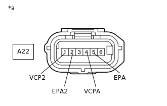
*a
Front view of wire harness connector
(to Accelerator Pedal Sensor Assembly)
Disconnect the accelerator pedal sensor assembly connector.
Turn the ignition switch to ON.
Measure the voltage according to the value(s) in the table below.
Standard Voltage
Tester Connection
Condition
Specified Condition
A22-1 (VCP2) - A22-2 (EPA2)
Ignition switch ON
4.5 to 5.5 V
A22-4 (VCPA) - A22-5 (EPA)
Ignition switch ON
4.5 to 5.5 V
Result
Proceed to
OK
NG