СИСТЕМА SFI, Diagnostic DTC:P0115/22, P0117/22, P0118/22
| DTC Code | DTC Name |
|---|---|
| P0115/22 | Engine Coolant Temperature Circuit |
| P0117/22 | Engine Coolant Temperature Circuit Low Input |
| P0118/22 | Engine Coolant Temperature Circuit High Input |
DESCRIPTION
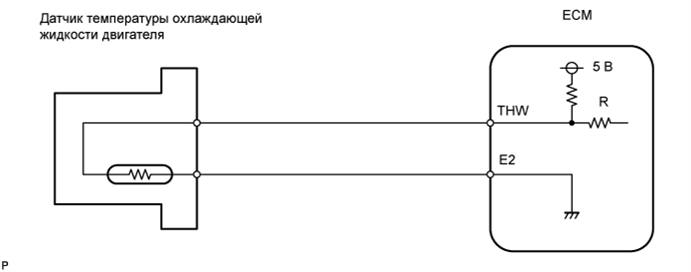
A thermistor is built into the Engine Coolant Temperature (ECT) sensor and changes its resistance value according to the engine coolant temperature.
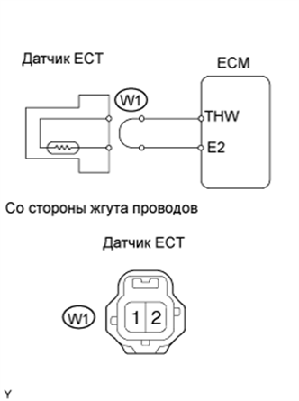
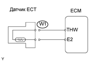
The structure of the sensor and its connection to the ECM is the same as that of the intake air temperature sensor and its connection.
Tech Tips
If the ECM detects DTC P0115/22, P0117/22 or P0118/22, the ECM enters fail-safe mode in which the ECT is assumed to be 80°C (176°F).
| DTC No. | DTC Detection Condition | Suspected Area |
|---|---|---|
| P0115/22 | Open or short in ECT sensor circuit for 0.5 seconds |
|
| P0117/22 | Short in ECT sensor circuit for 0.5 seconds |
|
| P0118/22 | Open in ECT sensor circuit for 0.5 seconds |
|
Tech Tips
When DTC P0115/22, P0117/22 or P0118/22 is detected, check the engine coolant temperature by entering the following menus on the intelligent tester: Powertrain / Engine and ECT / Data List / Coolant Temp.
| Temperature Displayed | Malfunction |
|---|---|
| -40°C (-40°F) | Open circuit |
| 140°C (284°F) or more | Short circuit |
MONITOR DESCRIPTION
The ECT sensor is used to monitor the engine coolant temperature. The ECT sensor has a thermistor that varies its resistance depending on the temperature of the engine coolant. When the coolant temperature is low, the resistance in the thermistor increases. When the temperature is high, the resistance drops. The variations in resistance are reflected in the voltage output from the sensor. The ECM monitors the sensor voltage and uses this value to calculate the ECT. When the sensor output voltage deviates from the normal operating range, the ECM interprets this as a fault in the ECT sensor and sets a DTC.
Example:
When the ECM calculates that the ECT is -40°C (-40°F) (P0118/22) or more than 140°C (284°F) (P0117/22) and that either condition continues for 0.5 seconds or more, the ECM will set a DTC.
This monitor runs for 0.5 seconds after the ignition switch is turned ON (1 trip detection logic).
WIRING DIAGRAM
INSPECTION PROCEDURE
Tech Tips
-
If DTCs related to different systems that have terminal E2 as the ground terminal are output simultaneously, terminal E2 may have an open circuit.
-
Read freeze frame data using the intelligent tester. Freeze frame data records the engine conditions when malfunctions are detected. When troubleshooting, freeze frame data can help determine if the vehicle was moving or stationary, if the engine was warmed up or not, if the air-fuel ratio was lean or rich, and other data from the time the malfunction occurred.
When using intelligent tester:
PROCEDURE
-
READ OUTPUT DTC
-
Connect the intelligent tester to the DLC3.
-
Turn the ignition switch ON and turn the intelligent tester ON.
-
Enter the following menus: Powertrain / Engine and ECT / DTC.
-
Read DTCs.
Result Display (DTC Output) Proceed to P0115/22 A P0117/22 B P0118/22 C
B 
READ DATA LIST (CHECK FOR SHORT IN WIRE HARNESS) Click here
C
READ DATA LIST (CHECK FOR OPEN IN WIRE HARNESS) Click here
A 
-
-
READ DATA LIST (ENGINE COOLANT TEMPERATURE)
-
Connect the intelligent tester to the DLC3.
-
Turn the ignition switch ON and turn the intelligent tester ON.
-
Enter the following menus: Powertrain / Engine and ECT / Data List / Coolant Temp.
-
Read the value.
OK Temperature value is 80 to 97°C (176 to 207°F) after warming up the engine. Result Temperature Displayed Proceed to -40°C (-40°F) A 140°C (284°F) or more B OK (same as the actual engine coolant temperature) C Tech Tips
-
If there is an open circuit, the intelligent tester indicates -40°C (-40°F).
-
If there is a short circuit, the intelligent tester indicates 140°C (284°F) or more.
-
B
READ DATA LIST (CHECK FOR SHORT IN WIRE HARNESS) Click here
C 
CHECK FOR INTERMITTENT PROBLEMS
A
-
-
READ DATA LIST (CHECK FOR OPEN IN WIRE HARNESS)
-
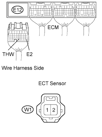
Disconnect the W1 ECT sensor connector.
-
Connect terminals 1 and 2 of the W1 ECT sensor wire harness side connector.
-
Turn the ignition switch ON and turn the intelligent tester ON.
-
Enter the following menus: Powertrain / Engine and ECT / Data List / Coolant Temp.
-
Read the value.
OK Temperature value is 140°C (284°F) or more
OK
CONFIRM GOOD CONNECTION AT SENSOR. IF OK, REPLACE ENGINE COOLANT TEMPERATURE SENSOR
NG
-
-
READ DATA LIST (CHECK FOR OPEN IN ECM)
-
Disconnect the W1 ECT sensor connector.
-
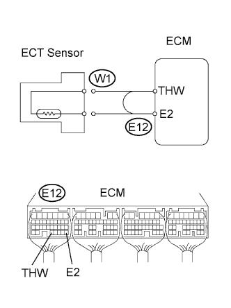
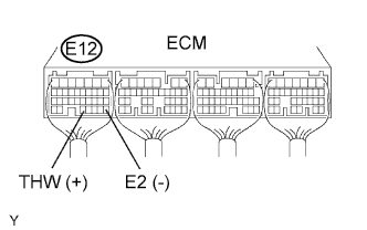
Connect terminals THW and E2 of the E12 ECM connector.
Tech Tips
Before checking, perform a visual and contact pressure check on the ECM connector.
-
Turn the ignition switch ON and turn the intelligent tester ON.
-
Enter the following menus: Powertrain / Engine and ECT / Data List / Coolant Temp.
-
Read the value.
OK Temperature value is 140°C (284°F) or more
OK
REPAIR OR REPLACE HARNESS AND CONNECTOR
NG 
CONFIRM GOOD CONNECTION AT ECM. IF OK, REPLACE ECM
-
-
READ DATA LIST (CHECK FOR SHORT IN WIRE HARNESS)
-
Disconnect the W1 ECT sensor connector.
-
Turn the ignition switch ON and turn the intelligent tester ON.
-
Enter the following menus: Powertrain / Engine and ECT / Data List / Coolant Temp.
-
Read the value.
OK Temperature value is -40°C (-40°F)
OK
REPLACE ENGINE COOLANT TEMPERATURE SENSOR
NG
-
-
CHECK WIRE HARNESS (ECM - ENGINE COOLANT TEMPERATURE SENSOR)
-
Disconnect the E12 ECM connector.
-
Disconnect the W1 ECT sensor connector.
-
Measure the resistance of the wire harness side connectors.
Standard resistance Tester Connection Specified Condition E12-32 (THW) - W1-2 Below 1 Ω E12-28 (E2) - W1-1 Below 1 Ω E12-32 (THW) or W1-2 - Body ground 10 kΩ or higher
NG
REPAIR OR REPLACE HARNESS AND CONNECTOR
OK
REPLACE ECM
-
When not using intelligent tester:
PROCEDURE
-
CHECK ECM (THW VOLTAGE)
-
Turn the ignition switch ON.
-
Measure the voltage between terminals THW and E2 of the ECM connector.
Standard voltage Engine Coolant Temperature Specified Condition 20°C (68°F) 0.5 to 3.4 V 80°C (176°F) 0.2 to 1.0 V
OK
CHECK FOR INTERMITTENT PROBLEMS
NG
-
-
INSPECT ENGINE COOLANT TEMPERATURE SENSOR
-
Inspect the ECT sensor Click here.
NG
REPLACE ENGINE COOLANT TEMPERATURE SENSOR
OK
-
-
CHECK WIRE HARNESS (ECM - ENGINE COOLANT TEMPERATURE SENSOR)
-
Disconnect the E12 ECM connector.
-
Disconnect the W1 ECT sensor connector.
-
Measure the resistance of the wire harness side connectors.
Standard resistance Tester Connection Specified Condition E12-32 (THW) - W1-2 Below 1 Ω E12-28 (E2) - W1-1 Below 1 Ω E12-32 (THW) or W1-2 - Body ground 10 kΩ or higher
NG
REPAIR OR REPLACE HARNESS AND CONNECTOR
OK
REPLACE ECM
-