BACK DOOR CLOSER SYSTEM Back Door cannot be Opened
| DTC Code | DTC Name |
|---|---|
| Back Door cannot be Opened |
DESCRIPTION
When the back door cannot be opened, one of the following may be malfunctioning: 1) multiplex network door ECU, 2) back door lock assembly, 3) back door opener switch assembly, 4) main body ECU (multiplex network body ECU), or 5) certification ECU (smart key ECU assembly).
WIRING DIAGRAM
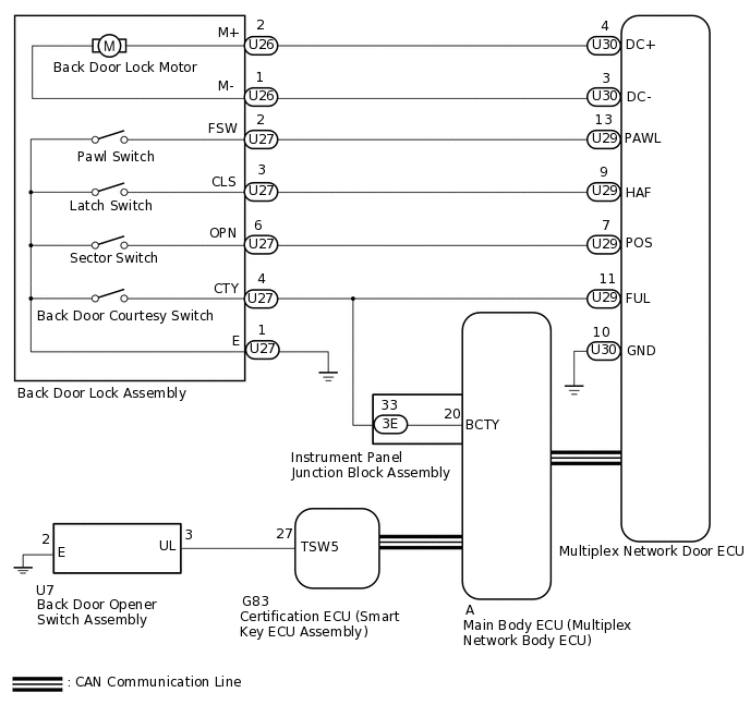
CAUTION / NOTICE / HINT
For vehicles with an entry and start system:
Before replacing the certification ECU (smart key ECU assembly), refer to the entry and start system.
The back door closer system uses the CAN communication system. First, confirm that there is no malfunction in the CAN communication system. Refer to the How to Proceed with Troubleshooting procedure.
When replacing the main body ECU (multiplex network body ECU), make sure to replace it with a new one.
If the replacement, removal and installation of the multiplex network door ECU or disconnection of the connectors of the multiplex network door ECU has been performed, initialize the power back door system.
PROCEDURE
CHECK FOR DTC
Check for DTCs.
Body Electrical > Back Door > Trouble Codes
Result
Proceed to
DTC is not output
DTC B2250 is output
DTC B2251 is output
BASIC FUNCTION POWER DOOR LOCK OPERATION
Check the power door lock basic function.
OK
The power door lock basic function can be operated normally.
Result
Proceed to
OK
NG
READ VALUE USING GTS
Check if the back door lock functions properly.
Body Electrical > Main Body > Data List
Tester Display
Measurement Item
Range
Normal Condition
Diagnostic Note
Back Door Open
Back door condition signal
Permit or Prohibit
Permit: Back door unlocked
Prohibit: Back door locked
-
Body Electrical > Main Body > Data List
Tester Display
Back Door Open
OK
The back door functions as specified in the normal condition column.
Result
Proceed to
OK
NG (for RHD)
NG (for LHD)
READ VALUE USING GTS
Check if the back door lock functions properly.
Body Electrical > Back Door > Data List
Tester Display
Measurement Item
Range
Normal Condition
Diagnostic Note
Door Lock Status
Back door condition signal
Lock or Unlock
Lock: Back door locked
Unlock: Back door unlocked
-
Body Electrical > Back Door > Data List
Tester Display
Door Lock Status
OK
The back door functions as specified in the normal condition column.
Result
Proceed to
OK
NG
READ VALUE USING GTS
Check if the back door opener switch assembly functions properly.
Body Electrical > Entry&Start > Data List
Tester Display
Measurement Item
Range
Normal Condition
Diagnostic Note
Tr/B-Door Lock SW
Back door opener switch assembly signal
ON or OFF
ON: Back door opener switch assembly on
OFF: Back door opener switch assembly off
-
Body Electrical > Smart Key > Data List
Tester Display
Tr/B-Door Unlock SW
OK
The back door control switch assembly functions as specified in the normal condition column.
Result
Proceed to
OK
NG
NG INSPECT BACK DOOR OPENER SWITCH ASSEMBLYClick here
INSPECT BACK DOOR LOCK ASSEMBLY
Remove the back door lock assembly.
Inspect the back door lock assembly.
Result
Proceed to
OK
NG
CHECK HARNESS AND CONNECTOR (BACK DOOR LOCK ASSEMBLY - MULTIPLEX NETWORK DOOR ECU AND BODY GROUND)
Disconnect the U26 and U27 back door lock assembly connector.
Disconnect the U30 and U29 multiplex network door ECU connectors.
Disconnect the 3E instrument panel junction block assembly connector.
Measure the resistance according to the value(s) in the table below.
Standard Resistance
Tester Connection
Condition
Specified Condition
U26-2 (M+) - U30-4 (DC+)
Always
Below 1 Ω
U26-1 (M-) - U30-3 (DC-)
Always
Below 1 Ω
U27-4 (CTY) - U29-11 (FUL)
Always
Below 1 Ω
U27-4 (CTY) - 3E-33
Always
Below 1 Ω
U27-2 (FSW) - U29-13 (PAWL)
Always
Below 1 Ω
U27-3 (CLS) - U29-9 (HAF)
Always
Below 1 Ω
U27-6 (OPN) - U29-7 (POS)
Always
Below 1 Ω
U27-1 (E) - Body ground
Always
Below 1 Ω
U26-2 (M+) or U30-4 (DC+) - Body ground
Always
10 kΩ or higher
U26-1 (M-) or U30-3 (DC-) - Body ground
Always
10 kΩ or higher
U27-2 (FSW) or U29-13 (PAWL) - Body ground
Always
10 kΩ or higher
U27-4 (CTY) or U29-11 (FUL) - Body ground
Always
10 kΩ or higher
U27-4 (CTY) or 3E-33 - Body ground
Always
10 kΩ or higher
U27-3 (CLS) or U29-9 (HAF) - Body ground
Always
10 kΩ or higher
U27-6 (OPN) or U29-7 (POS) - Body ground
Always
10 kΩ or higher
Result
Proceed to
OK
NG
NG REPAIR OR REPLACE HARNESS OR CONNECTOR
REPLACE MULTIPLEX NETWORK DOOR ECU
Temporarily replace the multiplex network door ECU with a new or normally functioning one.
Result
Proceed to
NEXT
CHECK BACK DOOR CLOSER SYSTEM
Check the back door open operation.
Result
Proceed to
Back door can be opened
Back door cannot be opened (for RHD)
Back door cannot be opened (for LHD)
Back door can be opened END (MULTIPLEX NETWORK DOOR ECU WAS DEFECTIVE)
INSPECT BACK DOOR OPENER SWITCH ASSEMBLY
Remove the back door opener switch assembly.
Inspect the back door opener switch assembly.
Result
Proceed to
OK
NG
CHECK HARNESS AND CONNECTOR (BACK DOOR OPENER SWITCH ASSEMBLY - CERTIFICATION ECU AND BODY GROUND)
Disconnect the U7 back door opener switch assembly connector.
Disconnect the G83 certification ECU (smart key ECU assembly) connector.
Measure the resistance according to the value(s) in the table below.
Standard Resistance
Tester Connection
Condition
Specified Condition
U7-3 (UL) - G83-27 (TSW5)
Always
Below 1 Ω
U7-2 (E) - Body ground
Always
Below 1 Ω
U7-3 (UL) or G83-27 (TSW5) - Body ground
Always
10 kΩ or higher
Result
Proceed to
OK
NG
OK REPLACE CERTIFICATION ECU (SMART KEY ECU ASSEMBLY)
NG REPAIR OR REPLACE HARNESS OR CONNECTOR